Air hypocaust structure for cooling and/or heating

a technology of air hypocaust and structure, which is applied in the direction of air heaters, lighting and heating apparatus, heating types, etc., can solve the problems of reducing the heat transfer efficiency of the hypocaust system, leaking, and easy blockage or corrosion, and a lot of labor and repair costs are needed to repair the broken pip

Inactive Publication Date: 2006-06-27
HASTOPIA SHINYUNG
View PDF6 Cites 4 Cited by
  • Summary
  • Abstract
  • Description
  • Claims
  • Application Information

AI Technical Summary

Benefits of technology

The invention relates to an apparatus for guiding or positioning objects during manufacturing processes. Each guide plate has a special type of material that makes it easy to attach onto the top surface of the plate. This allows for precise placement of the object being worked on by the machine.

Problems solved by technology

This patent describes a method for improving the performance of a heating/cooling system that uses a concrete layer around a pipe. While this helps prevent blockages caused by rainwater, it also reduces energy loss due to poor thermal conduction. Additionally, the use of a thicker concrete layer can improve heat exchange efficiency without requiring extra maintenance work.

Method used


Image

  • Air hypocaust structure for cooling and/or heating
  • Air hypocaust structure for cooling and/or heating
  • Air hypocaust structure for cooling and/or heating

Examples


Embodiment Construction

[0017]Reference will now be made in detail to the present preferred embodiments of the present invention, examples of which are illustrated in the accompanying drawings, wherein like reference numerals refer to like elements throughout.

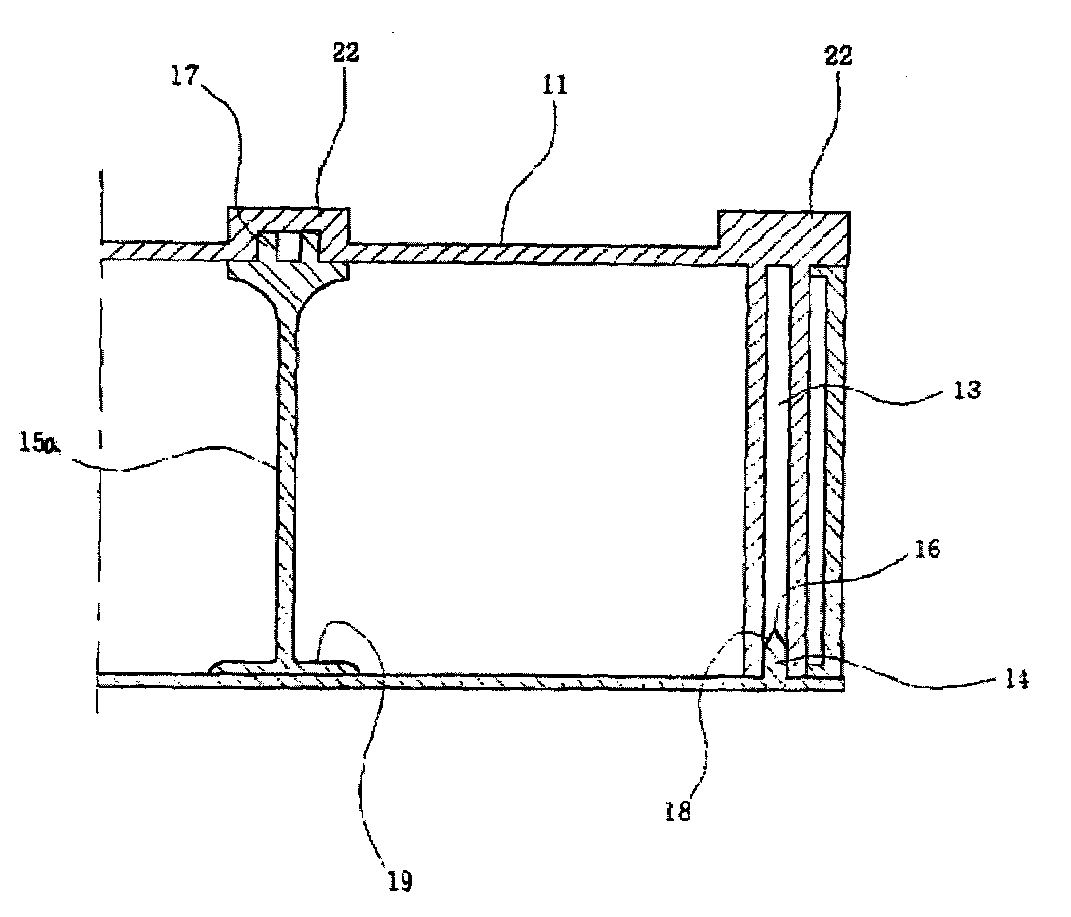
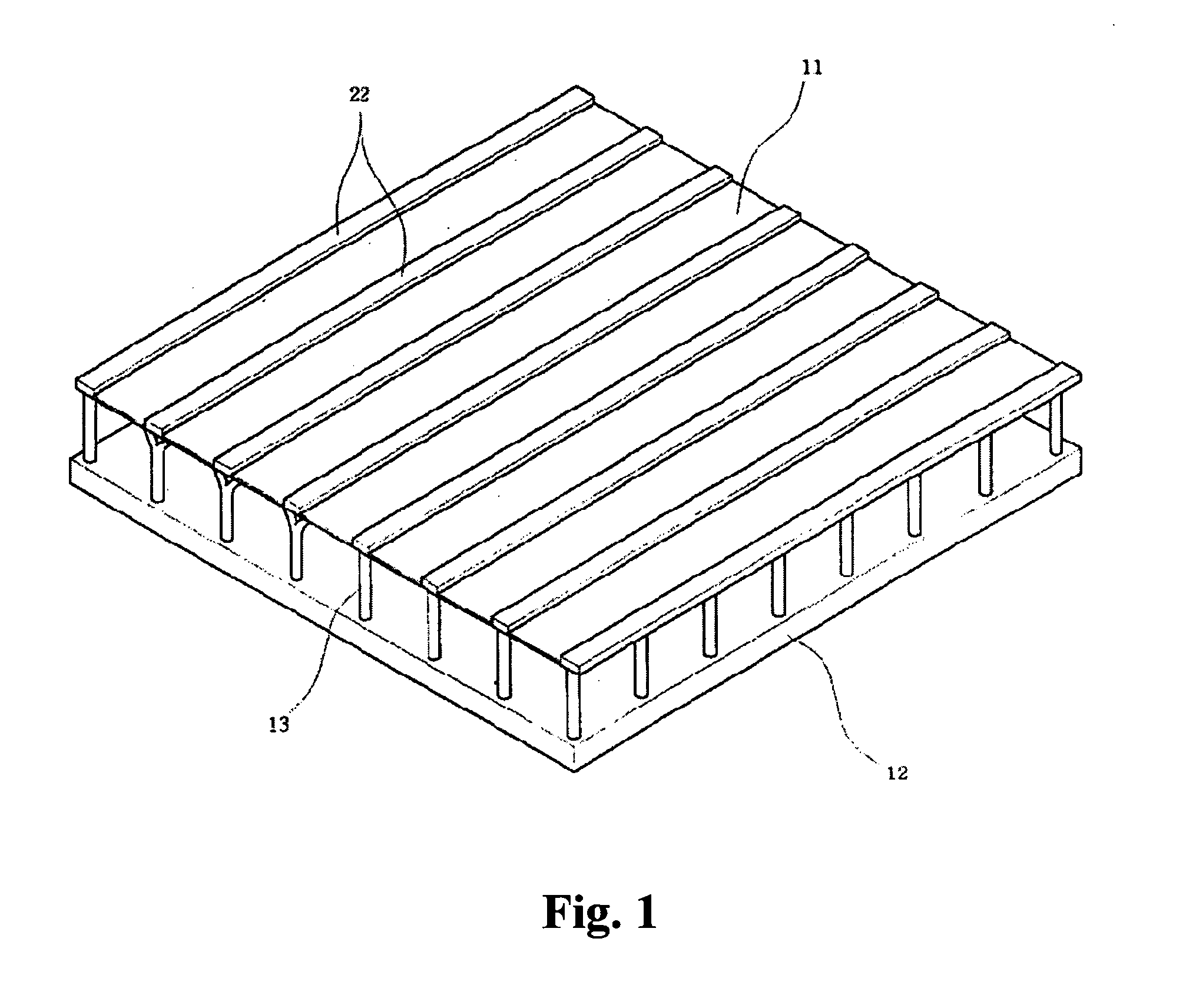
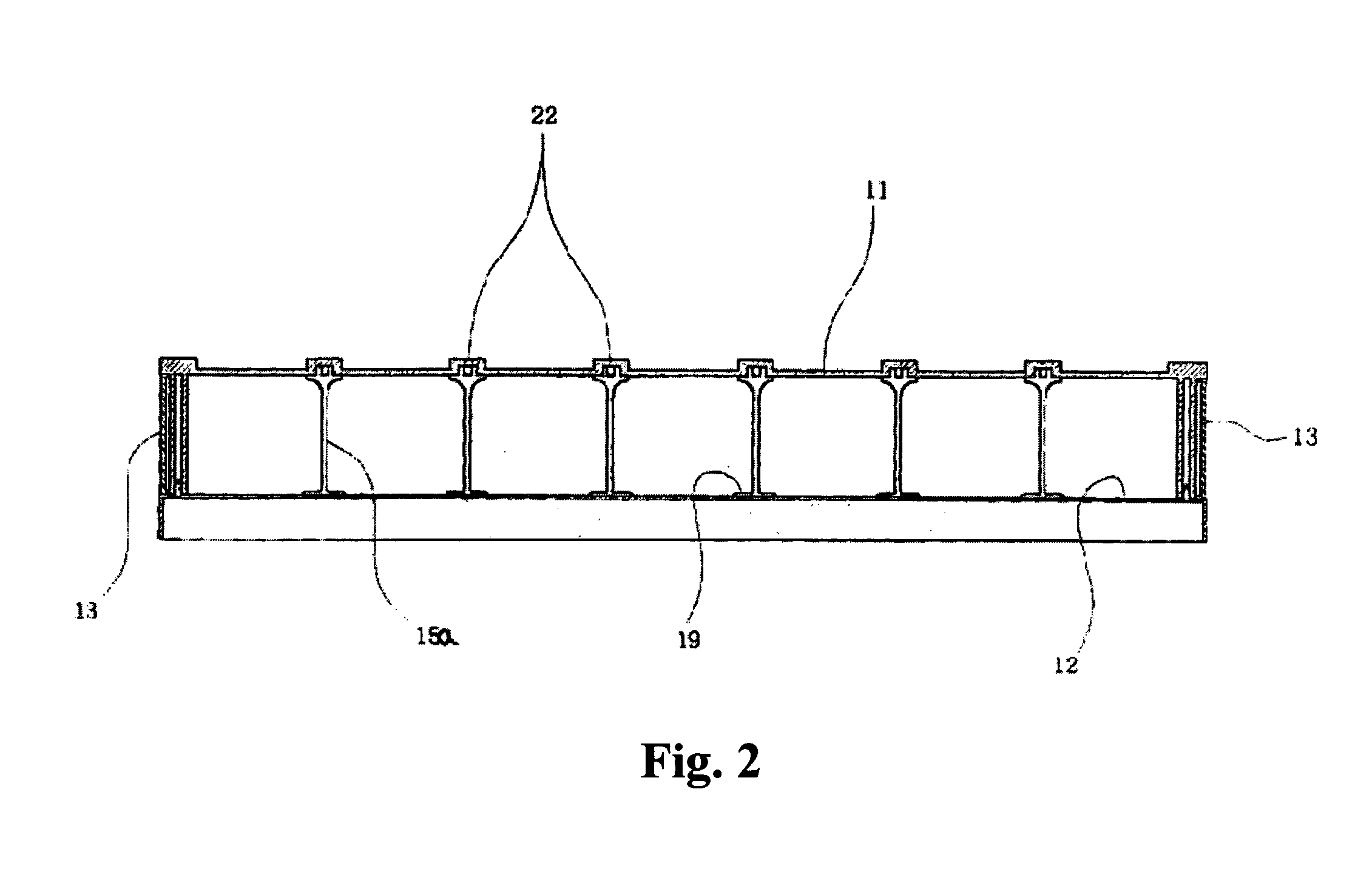
[0018]As shown in FIGS. 1 and 2, the present invention is characterized in that an air hypocaust structure includes an upper plate 11 having a plurality of recess parts 17 positioned at regular intervals, and integrally provided with a plurality of support legs 13 positioned along an edge thereof at regular intervals, a base plate 12 provided with a plurality of projections 14 corresponding in position to the support legs 13, and a plurality of curved and straight guide plates 15a and 15b selectively installed between the upper plate 11 and the base plate 12, thereby controlling a flow direction of a cold or a hot air current.

[0019]By the use of the air hypocaust structure according to the present invention, a dwelling is cooled or heated by a conduction


PUM


Abstract

Disclosed is herein an air hypocaust structure for cooling and/or heating dwellings. In winter, hot air is supplied into a space between an upper and a base plate constituting the air hypocaust structure to heat the dwelling according to a convection and a radiation mechanism. In summer, cold air is supplied to the space between the upper and base plate to cool the dwelling according to the convection mechanism. A plurality of support legs and guide plates are installed between the upper and base plate, and the support legs and guide plates may be integrally formed on the lower side of the upper plate or may be separately produced to be assembled with the upper plate. A hole is formed at a lower end of each of the support legs, and projections each having a sharp tip at an end thereof and corresponding in position to the support legs are formed on the upper side of the base plate. Therefore, when the upper plate is assembled with the base plate, the sharp tips of the projections are inserted into the holes of the support legs to firmly assemble the upper plate with the base plate. Furthermore, the guide plates are arranged between the upper and base plate to control the direction of a hot or cold air current flowing through the air hypocaust structure.

Description


Claims


Application Information

Patent Timeline
Owner HASTOPIA SHINYUNG
Why Eureka
Try Eureka