Multifunction flashlight

a flashlight and multi-functional technology, applied in the field of multi-functional flashlights, can solve the problems of dead or low-voltage batteries, flashlights used in emergency situations, inattention,

Inactive Publication Date: 2006-07-04
MUHLNICKEL JR DONALD L
View PDF11 Cites 26 Cited by
  • Summary
  • Abstract
  • Description
  • Claims
  • Application Information

AI Technical Summary

Benefits of technology

This patent describes an improved flashlight that can hold things like batteries or bulbs for easy monitoring by means of a compass. It has a larger diameter cylinder made up of two parts - one part holding the battery and another part connecting it to the bulb. A cover called a middle cap is also included on top of this smaller component. There are also compressed springs placed between the middle cap and the battery to keep them in good contact with the light reflecting surface.

Problems solved by technology

This patent describes various technical improvements over existing flashlight designs. These improvements aim to improve upon certain aspects like convenience and functionality. Specifically, they focus on improving the design of flashlights to make them easier to install and replace batteries even if it becomes necessary due to environmental concerns. Additionally, they address the issue of insufficient power supply during emergency scenarios where users are forced to leave the flashlight behind. There is a need for a flashlight that can easily store replacement batteries, medication, or other materials without compromising the function of the flashlight itself.

Method used


Image

  • Multifunction flashlight
  • Multifunction flashlight
  • Multifunction flashlight

Examples


Embodiment Construction

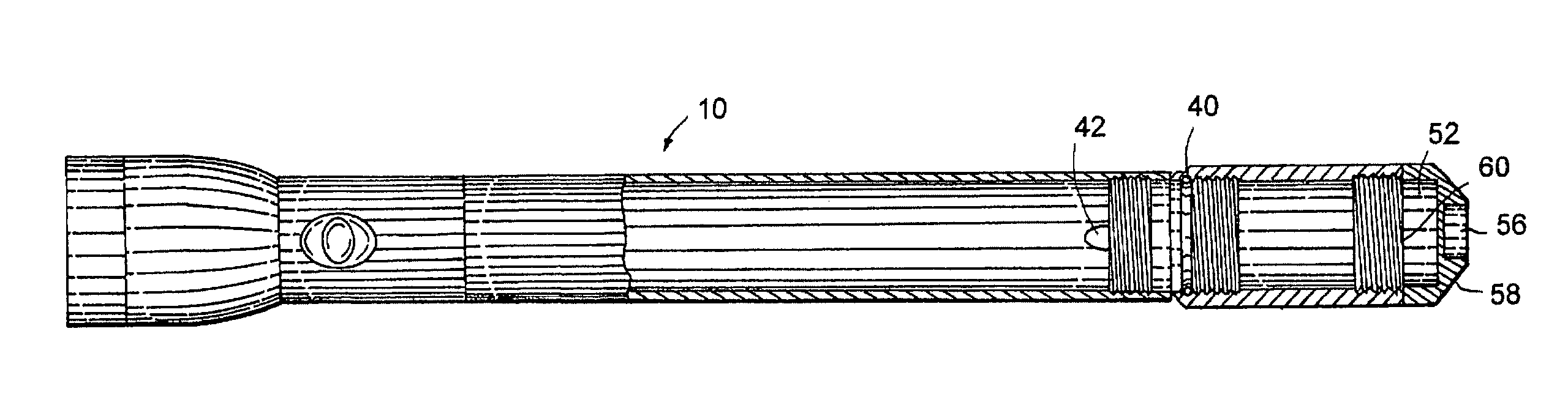
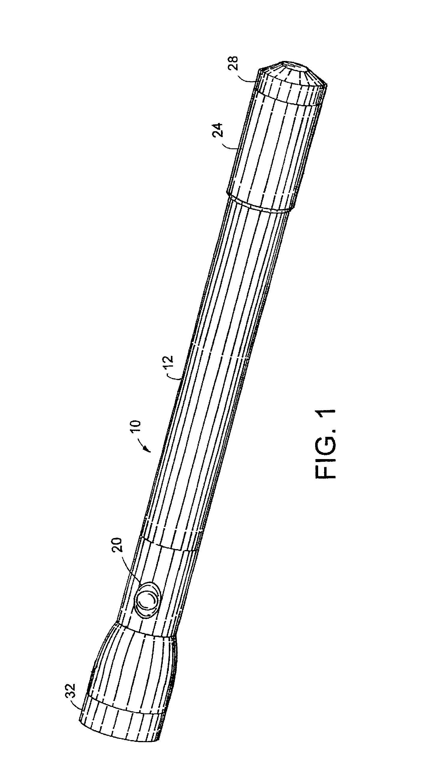
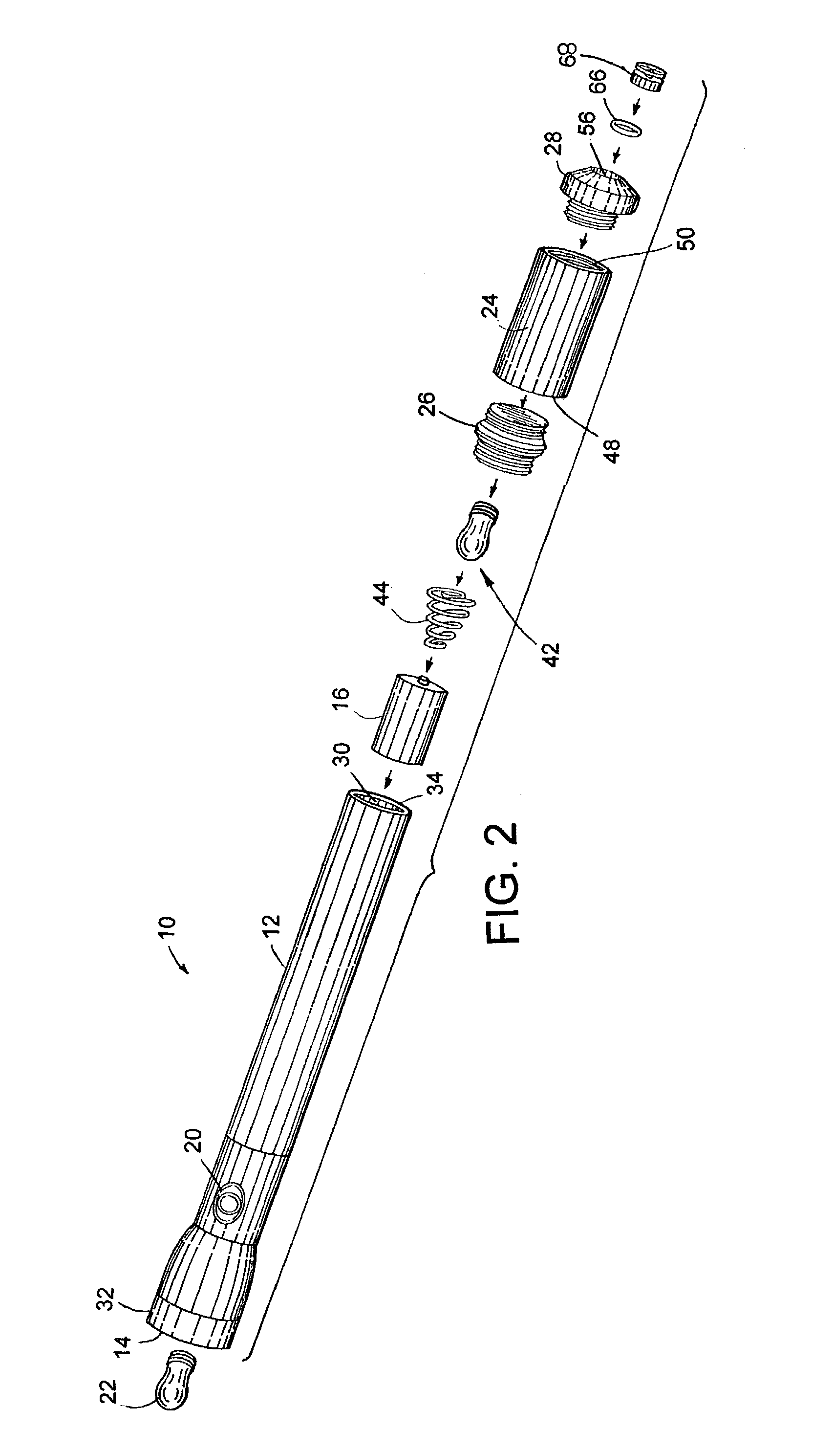
[0020]As shown in the exemplary drawings, and particularly in FIGS. 1 and 2, the invention is embodied in a flashlight (10) including a tubular body (12), a light reflector (14), a battery (16), an electrical circuit not shown including a switch (20), a light bulb (22), a cylindrical piggyback member (24) having a greater diameter than the tubular body, an intermediate cap (26), and an end cap (28). The tubular body, defining a space (30) in which the battery is maintained. The tubular body has a head end (32) and an intermediate end (34). The light reflector structure is secured to the head end portion of the tubular body and the light bulb is secured in the light reflector structure. Power from the battery is provided to the light bulb by the electrical circuit which may be interrupted by the switch. As shown by example in FIG. 6, the intermediate cap has an annular recess (72) which is configured with an annular groove (74) sized to receive an o-ring (78). The o-ring is sized to fri


PUM


Abstract

A flashlight having one or more storage areas while providing a means to attach useful accessories such as a can of pepper spray, compass or thermometer. The features of the invention allow the compass to be conveniently removed while still allowing the flashlight to operate. A portion of the storage area has a greater diameter than the tubular body of the flashlight to assist holding of the flashlight while separate storage spaces allow storing of spare batteries, light bulbs, other loose items or combinations of the like. In a separate feature of the invention, the intermediate cap has a cavity sized to receive and frictionally hold the flashlight.

Description


Claims


Application Information

Patent Timeline
Owner MUHLNICKEL JR DONALD L
Why Eureka
Try Eureka