Audio connector

a technology of audio connectors and connectors, applied in the direction of coupling device details, coupling device connections, electric discharge lamps, etc., can solve problems such as audio connectors to malfunction, and achieve the effect of not easily damaged

Inactive Publication Date: 2006-09-19
HUANG HUANG CHOU
View PDF8 Cites 10 Cited by
  • Summary
  • Abstract
  • Description
  • Claims
  • Application Information

AI Technical Summary

Benefits of technology

This patented design allows for easy damage-free connection between two devices without being affected or causing any problems during use. It uses special cases made up of different parts like conductive plates inside another box filled with rubber material. These boxes are designed to fit together tightly when they come loose due to vibrations caused by movement on uneven surfaces such as floors.

Problems solved by technology

This patented technical problem addressed in this patents relates to improving the performance of electrical devices like speakers used for generating sounds (such as television signals) due to issues related to incorrect alignment caused by external factors like vibrations during operation.

Method used


Image

  • Audio connector
  • Audio connector
  • Audio connector

Examples


Embodiment Construction

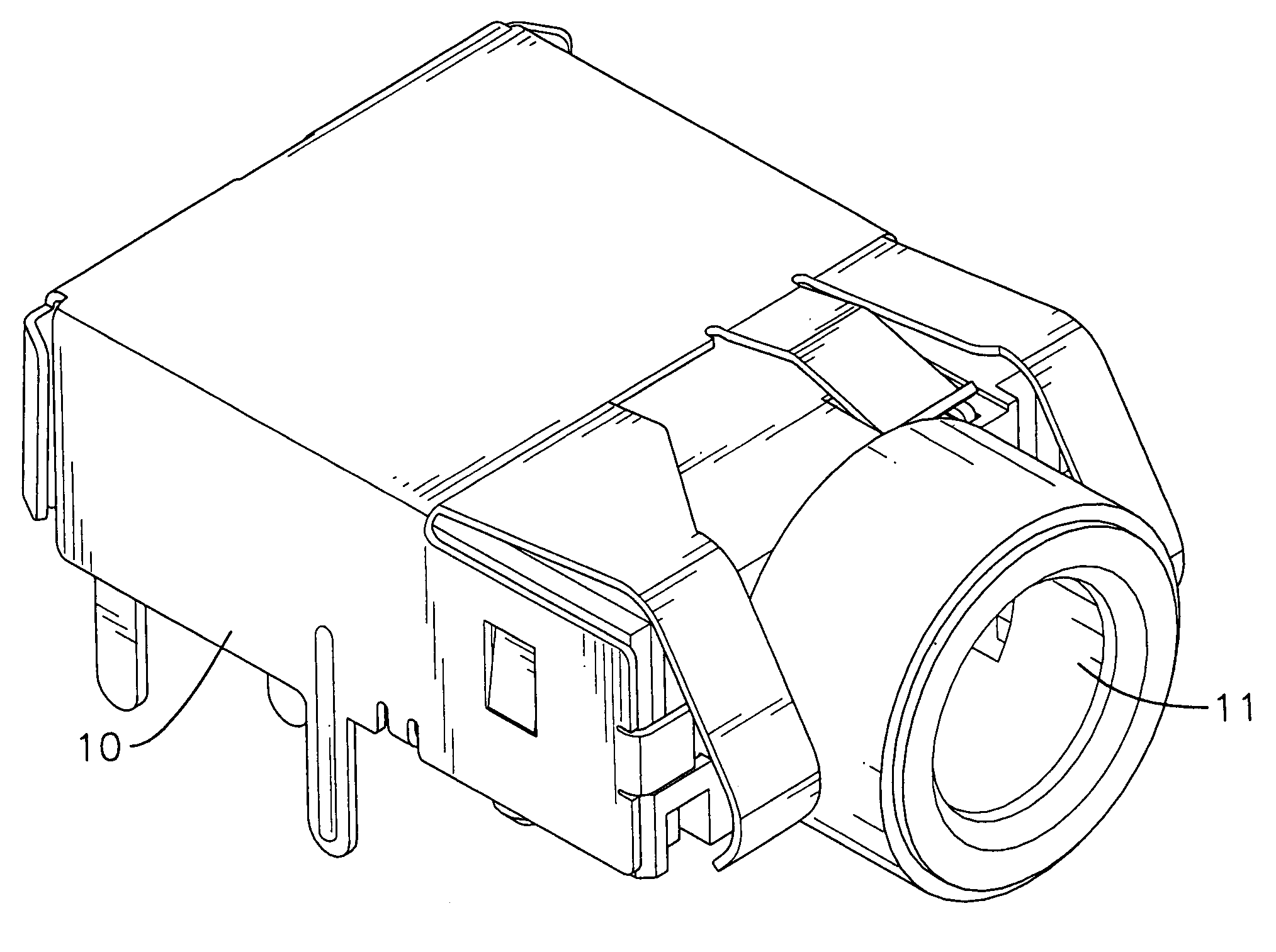
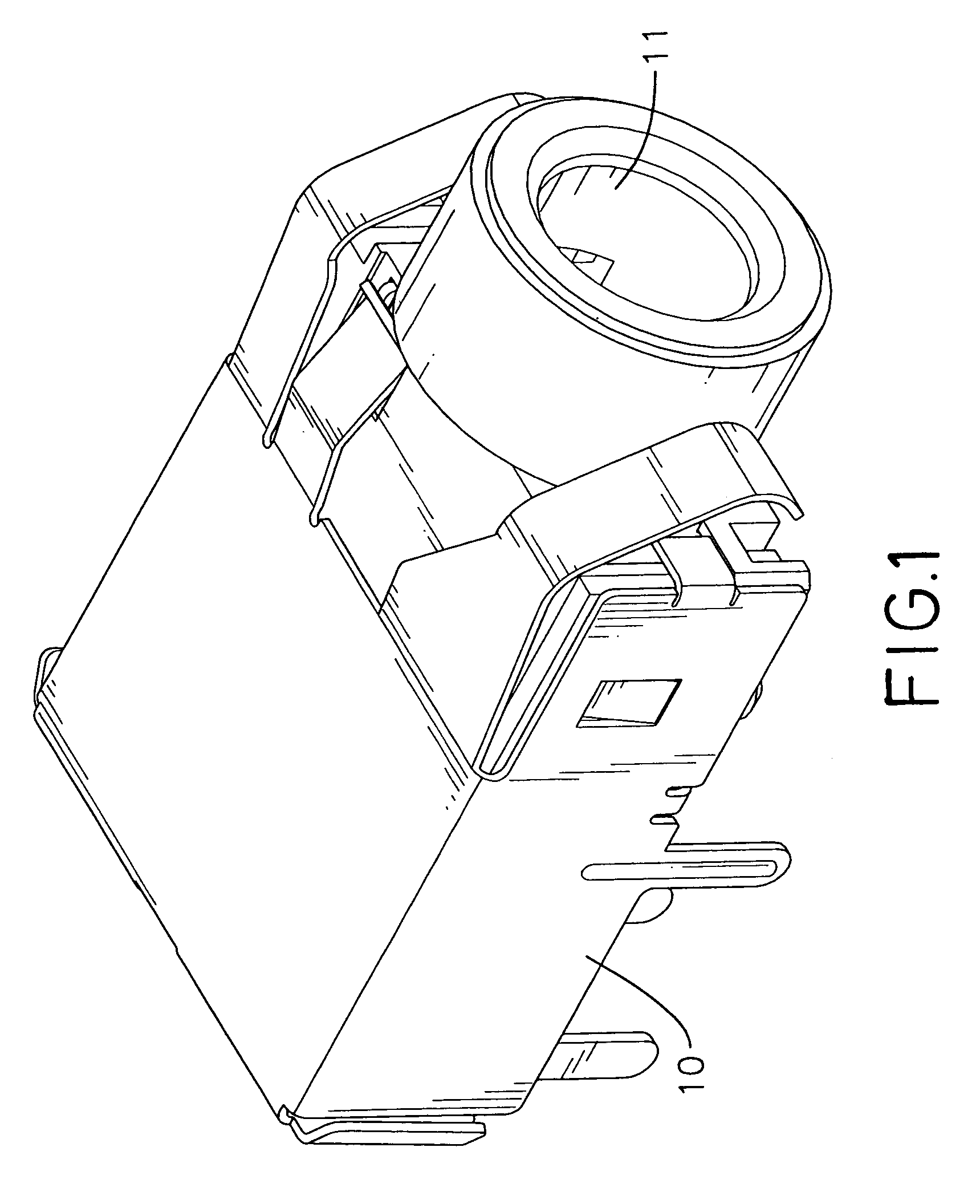
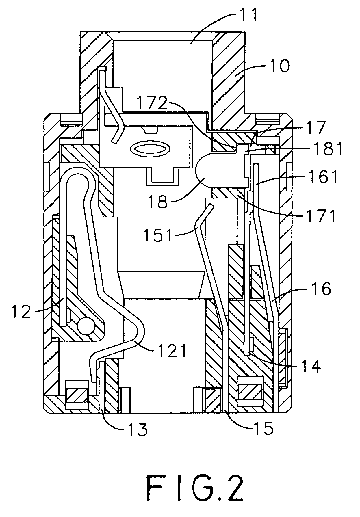
[0013]With reference to FIGS. 1 and 2, an audio connector in accordance with the present invention comprises an insulated case (10), an inner stationary contact (13), an inner resilient contact (12), an outer resilient contact (15), a resilient switch contact (16), a stationary switch contact (14) and a slide (18).

[0014]The insulated case (10) has an outer end, an inner end, a central socket (11), a first inner recess and a second inner recess. With further reference to FIG. 3, the central socket (ii) is formed through the insulated case (10) to accommodate a jack (20) to be seated in the audio connector. The first inner recess is formed in the insulated case (10) at the inner end, communicates with the central socket (11) and has an inner end. The second inner recess is formed in the insulated case (10) at the inner end, communicates with the socket (11) and has an inner end, an outer end and a guide channel (17). The guide channel (17) is formed near the outer end of the second inner


PUM


Abstract

An audio connector has an insulated case, an inner and outer contact and a slide. The insulated case has a central socket and second and first inner recesses that communicate with the central socket. The second inner recess has a guide channel. The inner contact is mounted in the first inner recess and selectively protrudes into the central socket. The outer contact is mounted in the second inner recess, and has an outer resilient contact, a resilient switch contact and a stationary switch contact. The outer resilient contact selectively protrudes into the central socket. The resilient switch contact has a distal end that aligns with the guide channel. The slide is mounted movably in the guide channel and is pressed into the central socket by the resilient switch contact. When a jack is inserted into the central socket, the slide keeps the jack from damaging the outer resilient contact.

Description


Claims


Application Information

Patent Timeline
Owner HUANG HUANG CHOU
Why Eureka
Try Eureka