Portable screen assembly

Active Publication Date: 2008-01-08
CAMERON RONALD A +1
View PDF18 Cites 20 Cited by
  • Summary
  • Abstract
  • Description
  • Claims
  • Application Information

AI Technical Summary

Benefits of technology

[0017]In view of the insufficiencies discussed above, it is an object of the present invention to provide a portable projecto

Problems solved by technology

Assembly is typically tedious, involving setting up a stand and unrolling the projection screen.
Such assemblies typically need to provide a sizable viewing area for projection equipment, and as a result are generally large and bulky and do not to break down to a very compact size.
Consequently, the image being displayed is distorted.
Furthermore, conventional portable projection screen assemblies tend to lack sturdiness.
Such a device cannot be stored compactly, and is bulky and impractical.
Projector assemblies that do not include roller m

Method used


Image

  • Portable screen assembly
  • Portable screen assembly
  • Portable screen assembly

Examples


Embodiment Construction

[0050]While this invention is susceptible of embodiments in many different forms, there is shown in the drawings and will herein be described in detail preferred embodiments of the invention with the understanding that the present disclosure is to be considered as an exemplification of the principles of the invention and is not intended to limit the broad aspect of the invention to the embodiments illustrated.

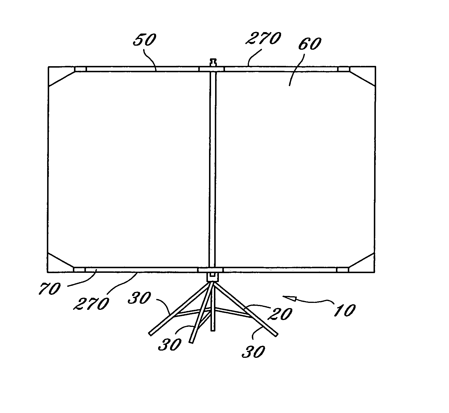
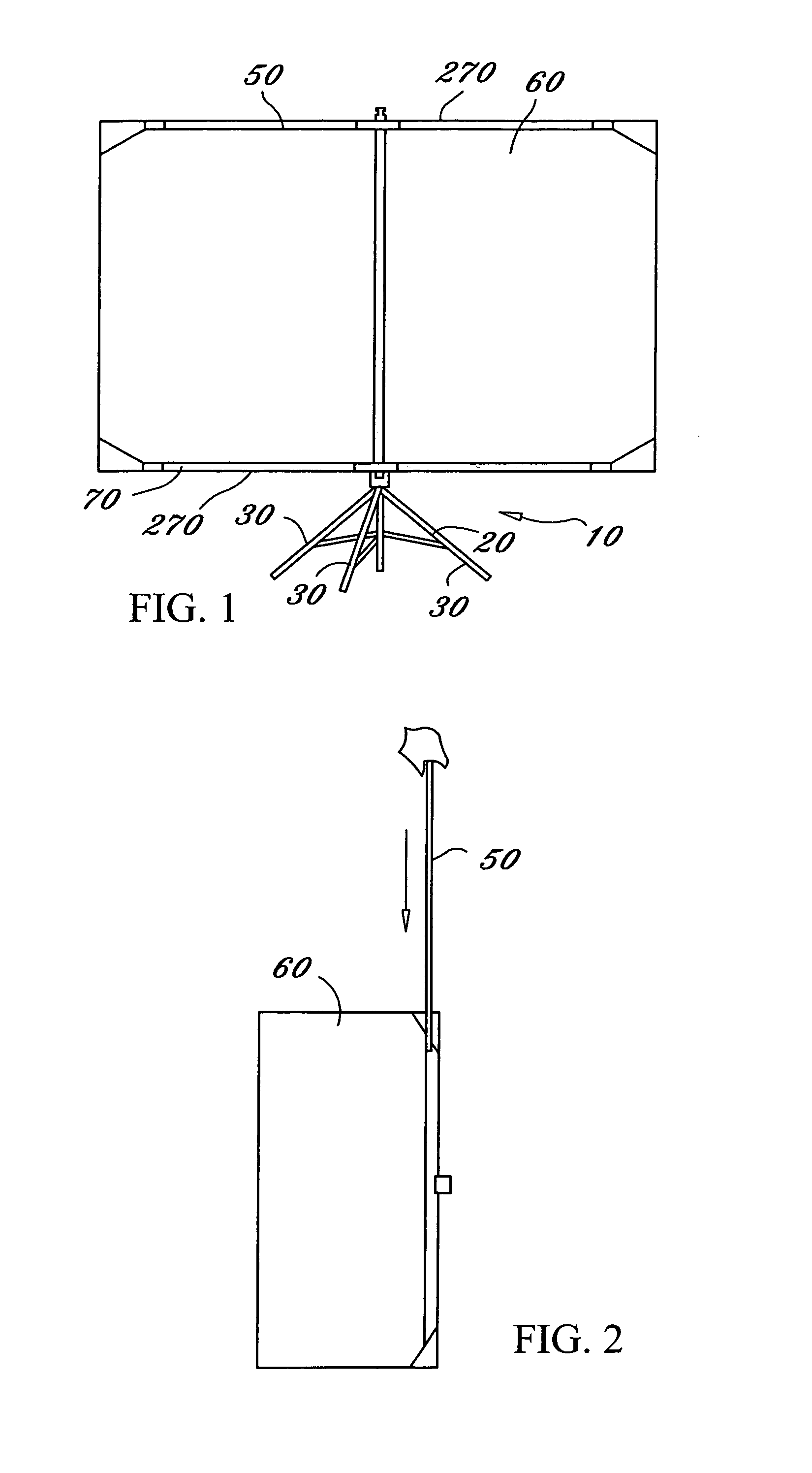
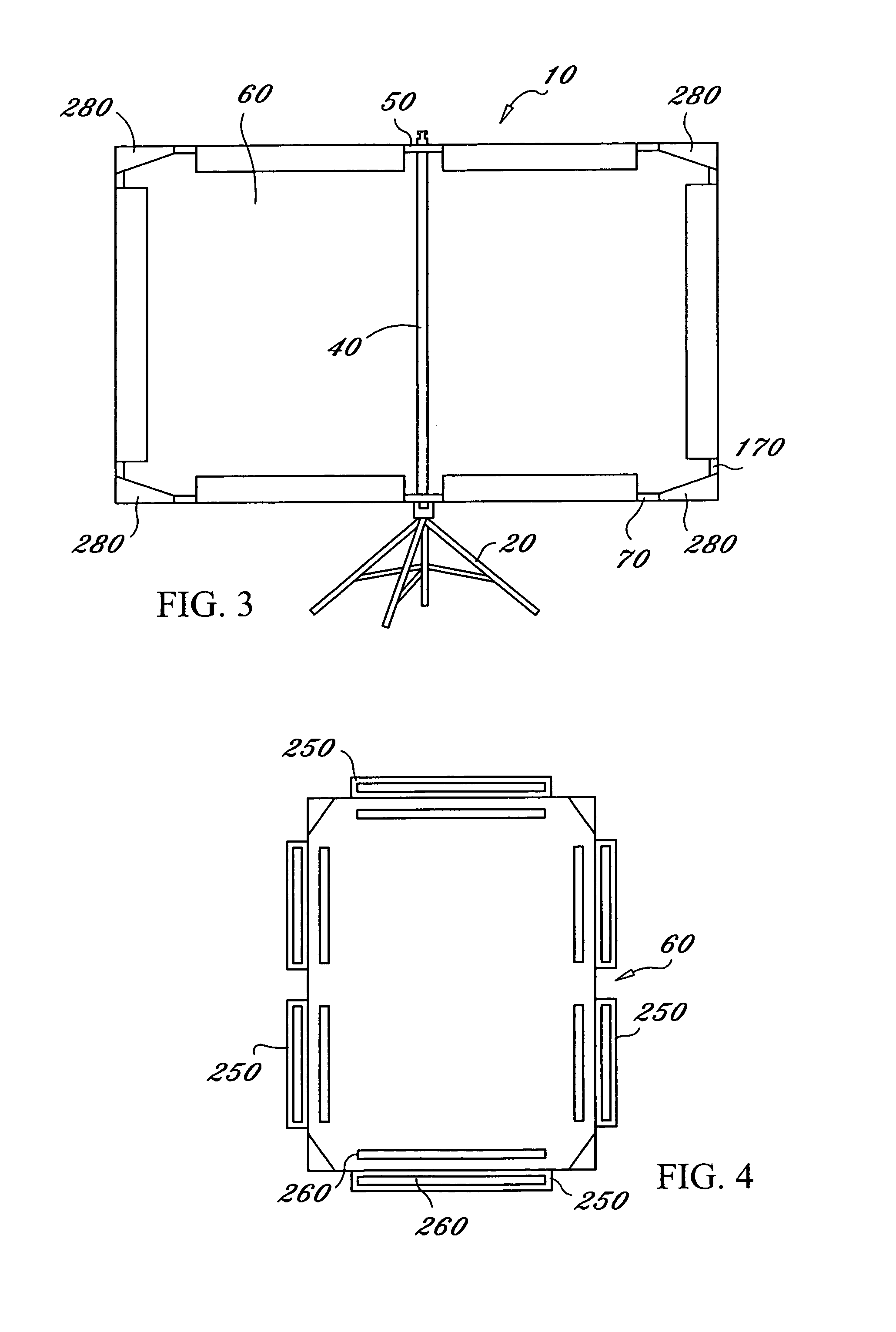
[0051]In a preferred embodiment, the present invention is a portable screen assembly 10 having a base 20 with at least three leg members 30 hingedly attached to a central support pole 40. The leg members 30 are selectively outwardly pivotable to form a base of support. The bottom of the central support pole 40 optionally rests on the ground, or in the same plane as the bottom ends of the leg members 30, for additional support.

[0052]A top frame member 50 perpendicularly removably attached to a top end of the central support pole 40 for supporting a top side of a screen 60. A bottom


PUM


Abstract

A portable screen assembly which is easily assembled and highly compact when disassembled is provided. The assembly includes a collapsible base having at least three leg members and a central support pole. The assembly includes top and bottom frame members in parallel relation supported via the central support pole supporting a screen. The screen is held in place with the frame members via flaps, sleeves, or hooks and eyelets, and is completely removable and preferably wrinkle resistant. Side supports are optionally included to provide additional support for the top and bottom frame members. The frame members and side supports are optionally telescoping members or frictionally fitting or threaded separable members. The top portion of the central support pole preferably includes a top cap which is part of a mounting mechanism for mounting the top frame member. In the preferred embodiment, the mounting mechanism allows for keystoning of the screen.

Description


Claims


Application Information

Patent Timeline
Owner CAMERON RONALD A
Why Eureka
Try Eureka