Low profile inlet for an implantable blood pump

a low-profile, blood-pump technology, applied in the direction of piston pumps, prostheses, therapy, etc., can solve the problems of reducing restricting the size of the pump, injury to the patient, etc., to improve the efficiency of the pump, improve the pump performance, and improve the effect of control

Inactive Publication Date: 2008-03-04
WORLD HEART
View PDF44 Cites 40 Cited by
  • Summary
  • Abstract
  • Description
  • Claims
  • Application Information

AI Technical Summary

Benefits of technology

The present invention provides a new design for a small pump that can improve its performance. It achieves this by making sure the fluid flows evenly throughout the pump's chamber while maintaining their speed. By adjusting the flow, there are fewer areas where they don't work properly or cause problems during use.

Problems solved by technology

The technical problem addressed in this patent is how to create a small but effective pump inlet for implantable blood pumps while minimizing their overall size and weight. Existing designs suffer from issues like excessive pressure drop caused by the infeed of blood, difficulty in controlling the flow direction of the blood, and instabilities during the pump's power usage. Therefore, there is a desire for a new pump design that can overcome these limitations and improve the safety and effectiveness of the pump.

Method used


Image

  • Low profile inlet for an implantable blood pump
  • Low profile inlet for an implantable blood pump
  • Low profile inlet for an implantable blood pump

Examples


Embodiment Construction

[0027]The presently preferred embodiments of the present invention will be best understood by reference to the drawings, wherein like parts are designated by like numerals throughout. It will be readily understood that the components of the present invention, as generally described and illustrated in the figures herein, could be arranged and designed in a wide variety of different configurations. Thus, the following more detailed description of the embodiments of the apparatus of the present invention, as represented in FIGS. 1 through 6, is not intended to limit the scope of the invention, as claimed, but is merely representative of presently preferred embodiments of the invention.

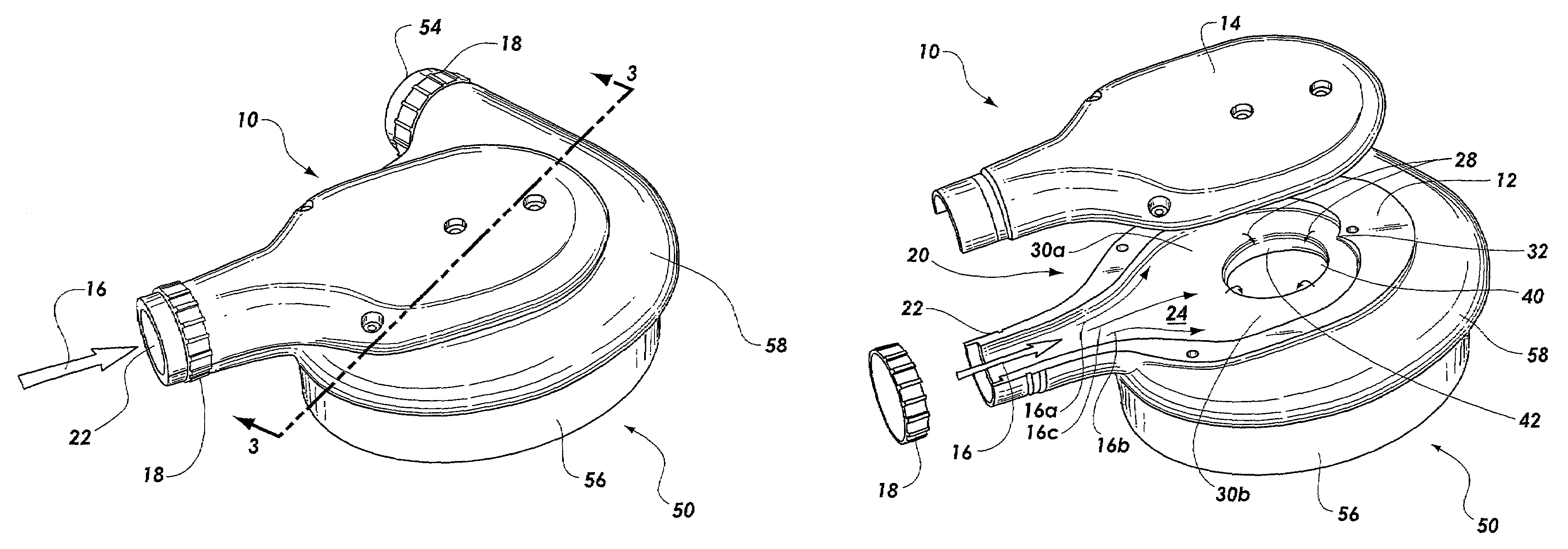
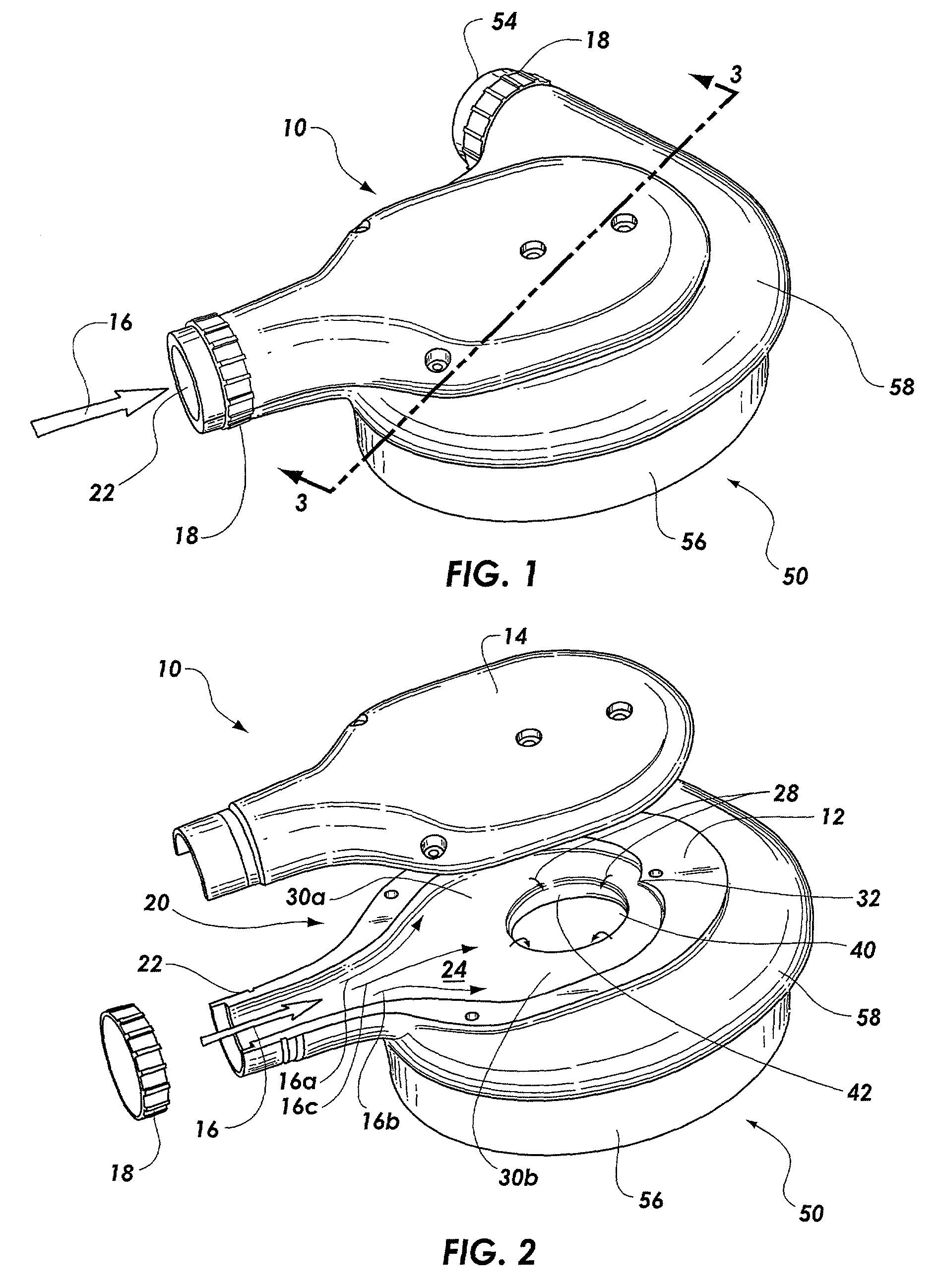
[0028]Referring now to FIG. 1, an implantable blood pump including a low profile pump inlet according to the invention is shown in perspective. Specifically, a pump inlet 10 is shown attached to an implantable blood pump 50. In this Figure, the pump inlet 10 is shown to include an inlet 22 and a coupling 18.


PUM


Abstract

A low profile pump inlet for an implantable blood pump is disclosed. The low profile pump inlet has an inflow diffuser for attachment to a conduit bearing an inflow of a fluid such as blood and an outflow orifice in fluid connection with the diffuser. The outflow orifice is configured to direct the fluid from the diffuser into a pump such as an implantable blood pump. The low profile pump inlet helps to suppress the effects of upstream pipe bends on the blood traveling through the inlet. The inlet thus provides a flow having a substantially uniform velocity profile into the blood pump.

Description


Claims


Application Information

Patent Timeline
Owner WORLD HEART
Why Eureka
Try Eureka