Switch feel measurement apparatus
a technology of feel and measurement apparatus, which is applied in the direction of apparatus for force/torque/work measurement, force measurement, instruments, etc., can solve the problems of inconvenient reconfiguring and re-aligning, expensive and time-consuming ways to measure the feel of switches, and conventional approaches that do not produce quantitative, objective, repeatable means for completely measuring the feel of switches. , to achieve the effect of minimizing the number of different parts required, minimizing the time needed to chang
- Summary
- Abstract
- Description
- Claims
- Application Information
AI Technical Summary
Benefits of technology
Problems solved by technology
Method used
Image

Examples
first embodiment
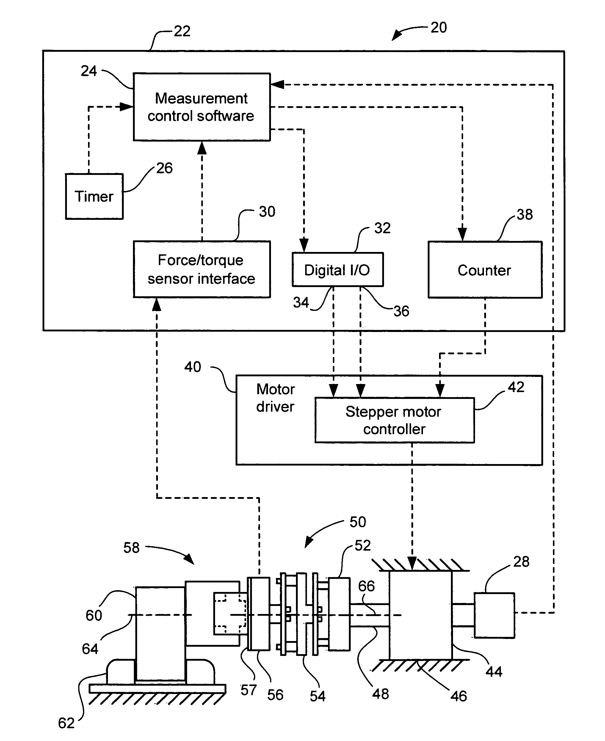
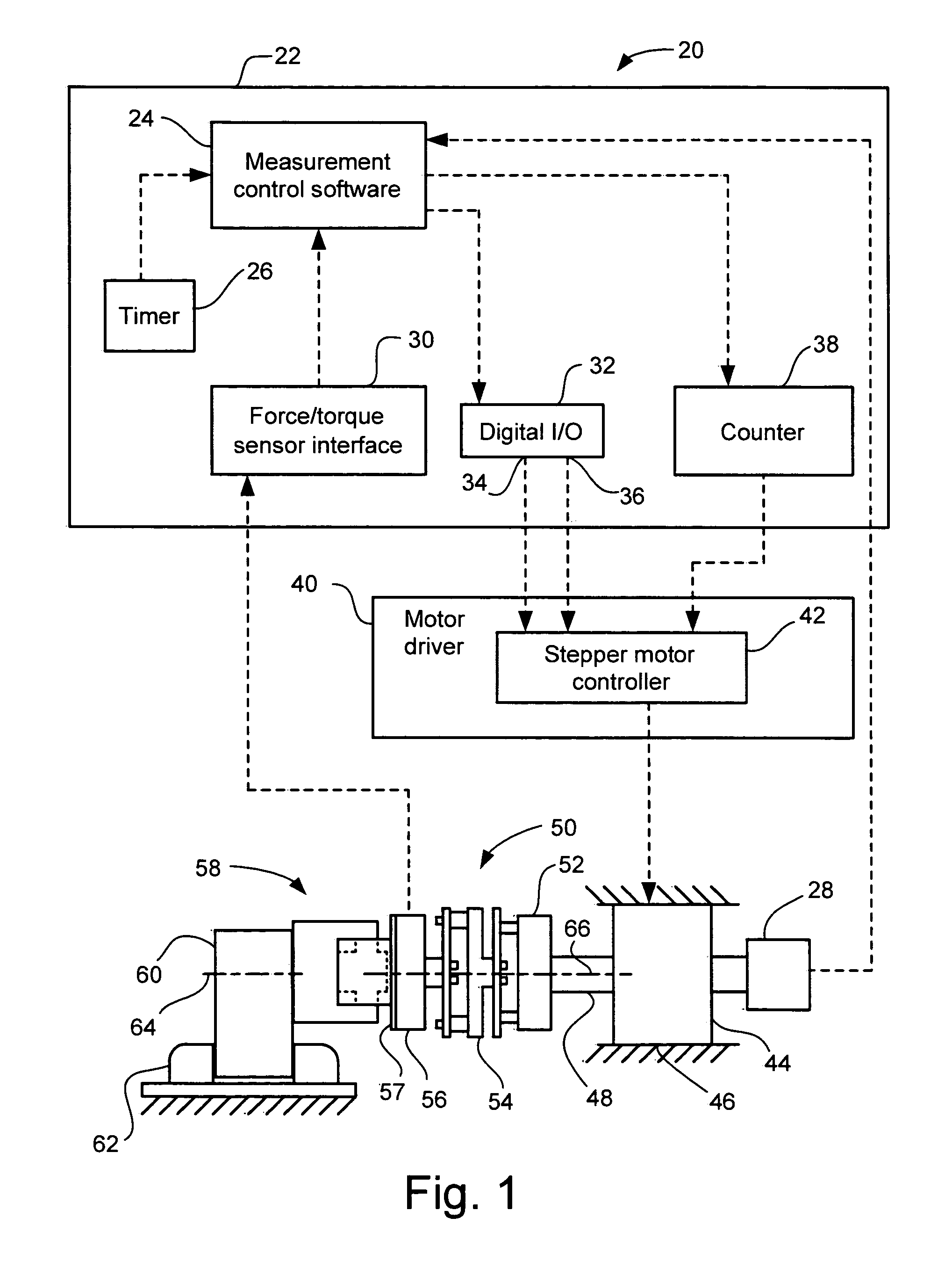
[0035]FIG. 2 illustrates the end effector 58, driven and controlled by the measurement unit 50 and switch measurement system 20, such as that disclosed in FIG. 1. This particular end effector 58 is employed to measure a thumbwheel 59 of a thumbwheel switch 60, which includes a switch base 61 mounted in the switch mounting support 62. Typically, in the past, thumbwheel switches were not measured because hardware capabilities did not exist for obtaining an accurate measurement.
[0036]The mounting hub 57 is mounted to the force / torque sensor 56, which includes an electrical connection 31 to the force / torque sensor interface (shown in FIG. 1). The end effector 58 also includes a short transverse shaft 68, mounted in and extending from a transverse mounting bore 69 in the mounting hub 57. This shaft 68 may be secured by a set screw or other conventional means (not shown). An extension bar 70 mounts to and extends from the short transverse shaft 68 parallel to the measurement axis 66. An
third embodiment
[0044]FIGS. 5 and 6 illustrate the end effector 258 for measuring a pivot arm 259 of a multifunction stalk switch 260. This embodiment has many elements in common with that of the previous embodiments, and to avoid unnecessary repetition of the description, the same reference numerals have been used for similar elements but falling within the 200-series. This embodiment employs a different end effector 258 that is particularly advantageous for measuring torque versus angular displacement for movement of the pivot arm 259 relative to the switch base 261.
[0045]A typical multifunctional stalk switch 260 to be measure has two pivoting degrees of freedom (e.g., headlamp flash and turn signal), plus at least one end rotary knob 279 (another degree of freedom) for other controls. In order to obtain meaningful torque versus annular displacement curves, the different degrees of freedom are measured independently. The end effector 258 shown in FIGS. 5 and 6 is for measuring pivoting of the pivot
fourth embodiment
[0048]FIGS. 7-12 illustrate an end effector kit 385 and some examples of various components of the kit being employed to measure different types of pivoting and rotary switches, according to a The end effector kit 385 and its components may be employed with a switch measuring system 20 such as that shown in FIG. 1. This embodiment has many elements in common with that of the previous embodiments, and to avoid unnecessary repetition of the description, the same reference numerals have been used for similar elements but falling within the 300-series. This end effector kit 385 is particularly advantageous for being able to quickly switch between different components of the kit to form various end effector assemblies that are well suited to generate accurate torque versus angular displacement curves for the particular type of switch being measured. Some examples of types of pivoting and rotary switches that may be measured include thumbwheel, push-pull, rocker, rotary knob, stalk pivot, a
PUM
 Abstract
Description
Claims
Application Information
 - R&D Engineer
- R&D Manager
- IP Professional
- Industry Leading Data Capabilities
- Powerful AI technology
- Patent DNA Extraction
Browse by: Latest US Patents, China's latest patents, Technical Efficacy Thesaurus, Application Domain, Technology Topic.
© 2024 PatSnap. All rights reserved.Legal|Privacy policy|Modern Slavery Act Transparency Statement|Sitemap