Large load carrier

a load carrier and large technology, applied in the field of large load carriers, can solve the problem that the foot parts occupy very little storage space, and achieve the effect of reducing storage space and reducing weigh

Inactive Publication Date: 2010-07-06
GEORG UTZ HOLDING AG
View PDF7 Cites 9 Cited by
  • Summary
  • Abstract
  • Description
  • Claims
  • Application Information

AI Technical Summary

Benefits of technology

The technical effect of this innovation is that it proposes replacing expensive loads with lighter protective materials like upright posts or plastic tubing instead for better durability without taking up too much room when stored.

Problems solved by technology

This patented technical problem addressed in this patents relates to lifting loads from tall shipping bases like those used at stores during peak hours when there may be high traffic levels due to frequent stops caused by drivers who move their tools around while carrying heavier loads. Additionally, current solutions involve placing loaded pallets directly upon steeples instead of rails, but they require costly equipment and increased storage capacity compared to flat palaces.

Method used


Image

  • Large load carrier
  • Large load carrier
  • Large load carrier

Examples


Embodiment Construction

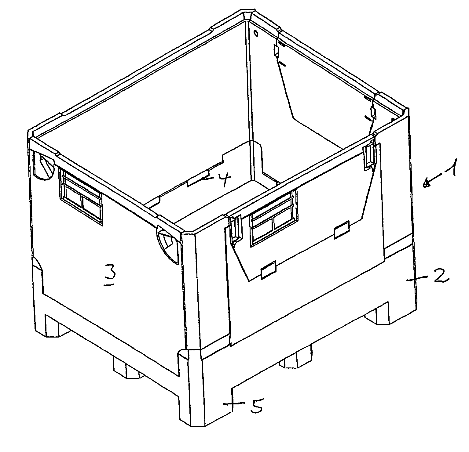
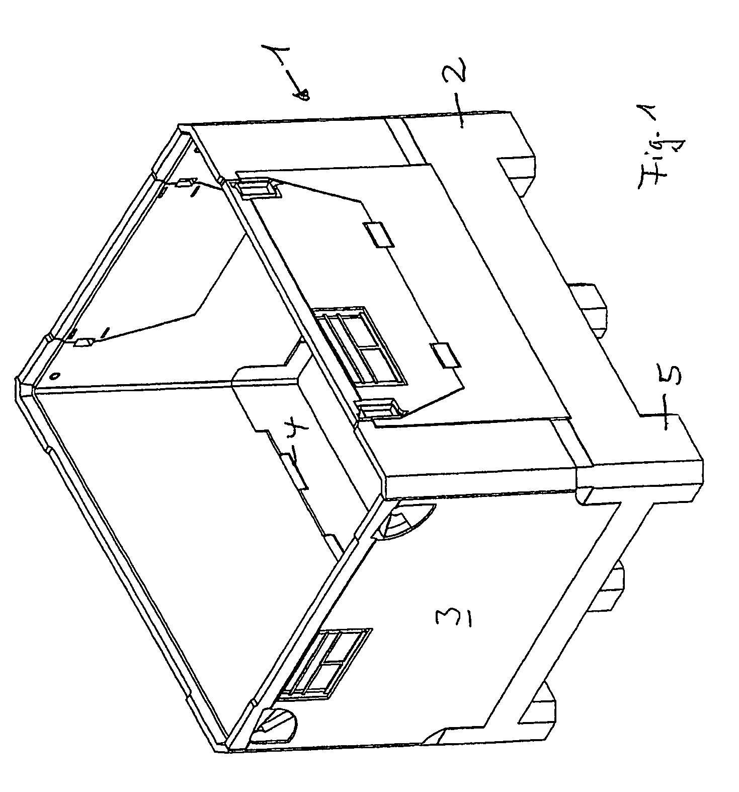
[0040]In FIG. 1 a large space container made of plastic is shown and indicated in general with the reference symbol 1. In the present case, the large space container 1 on a pallet base 2 is a folding box, in which the side walls 3 can be folded inward, about hinges 4.

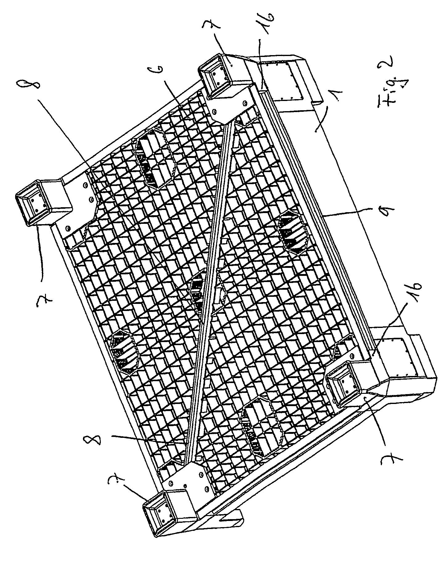
[0041]The pallet base, which is an integral part of the container 1, has standing feet 5, between which the fork of a forklift truck can be moved in.

[0042]The containers 1 are structured in such a manner that several can be stacked on top of one another, whereby the weight of such a stack can amount to several tons. For a forklift truck, it is practically impossible, in this case, to lift the stack in order to move its location, to move it, and to set it down again, for static reasons. For this reason, the forklift truck drivers set the tines of the fork of the forklift truck against the container 1 above the standing feet 5, and thereby displace the entire stack from one location to another. Since the previously known con


PUM


Abstract

A heavy load support made of plastic includes at least a rectangular bottom part with a leg part into which the fork of a forklift engages and which is provided with props located at least in the four corner areas of the bottom part. Metallic U-shaped profiled rails that are open towards the outside are provided between the props along the bottom edge of the load support. The props can be removably fixed to the bottom face of the bottom part of the load support and are provided with a support area for the corner areas of the bottom part as well as an edge which rises vertically from the support area and encloses the edges of the load support at a right angle, pegs being molded onto the free final leg surfaces of the edge to accommodate and fix the U-shaped profiled strips.

Description


Claims


Application Information

Patent Timeline
Owner GEORG UTZ HOLDING AG
Why Eureka
Try Eureka