Circuit adapted to supply a voltage to an electronic device and uses thereof

Inactive Publication Date: 2017-06-06
MANCIC MILAN +1
View PDF18 Cites 0 Cited by
  • Summary
  • Abstract
  • Description
  • Claims
  • Application Information

AI Technical Summary

Benefits of technology

[0011]Another object is to improve a driver light for light-emitting diodes, which improves the light intensity under the consumpti

Problems solved by technology

However, there is no disclosure of providing a circuit where it is possible at the output from the circuit to establish a normal o

Method used


Image

  • Circuit adapted to supply a voltage to an electronic device and uses thereof
  • Circuit adapted to supply a voltage to an electronic device and uses thereof
  • Circuit adapted to supply a voltage to an electronic device and uses thereof

Examples


Embodiment Construction

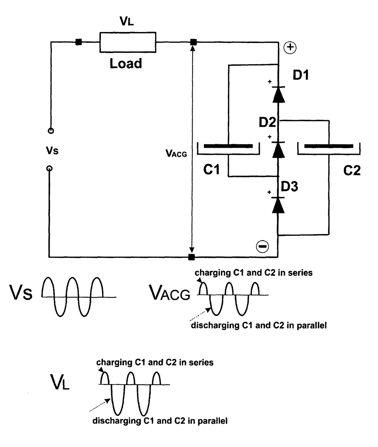
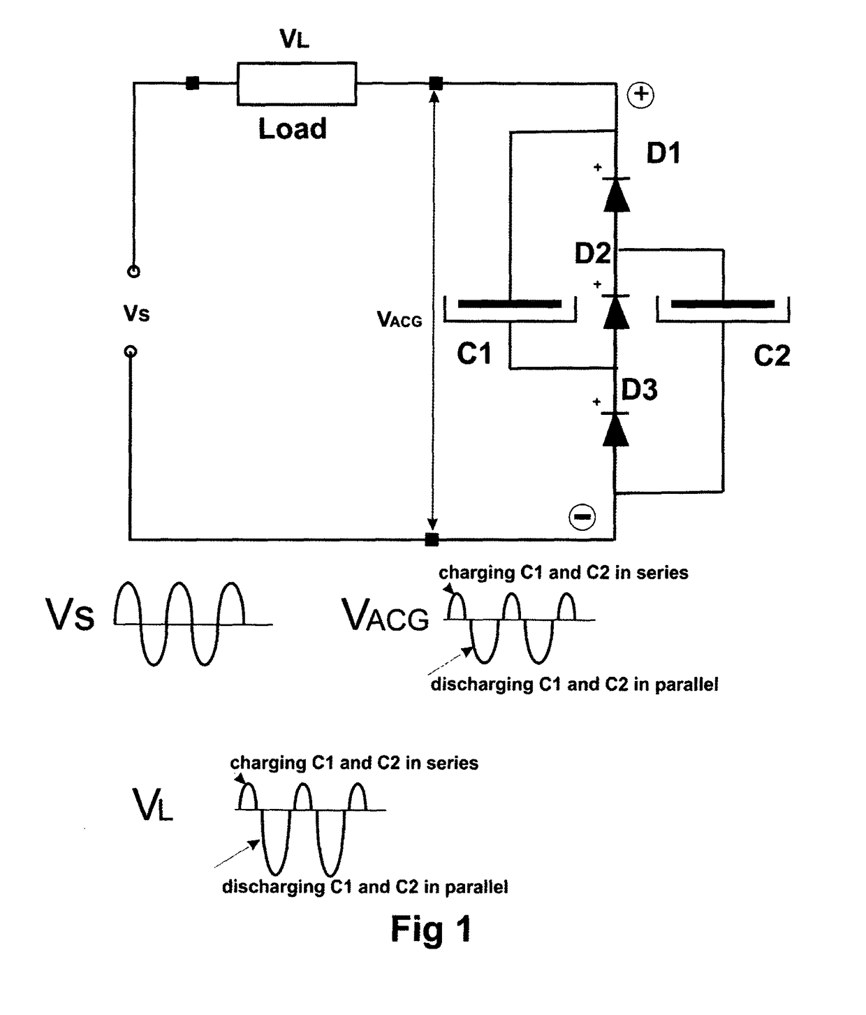
[0052]In FIG. 1 a circuit in the form of an Asymmetric Current Generator consisting of three diodes D1, D2, D3 are coupled in series. Two capacitors C1, C2 are coupled to the diodes, such that the capacitor C1 is coupled in parallel with the diodes D1,D2, whereas the capacitor C2 is coupled in parallel with the diodes D2 and D3.

[0053]This circuit is coupled to a voltage VS through the load VL said circuit operates as follows:

[0054]When the voltage Vs is applied to the load VL a voltage VACG is created at the output of the load VL.

[0055]The voltage Vs, is on the figure shown as a periodic symmetric sin signal.

[0056]The circuit operates as follows:

[0057]When the upper terminal of Vs is positive during the first half period, the capacitors C1, C2 will be charged during the first half period of Vs. The current will flow through the load VL and the serial part of the circuit consisting of the capacitor C1, the diode D2 and the capacitor C2, since diodes D1, D3 will not be open for current.

[


PUM


Abstract

In a circuit adapted to supply a voltage Vs an electronic device, such as a load or a light source said voltage Vs is led to a circuit (ACG) that is able to derive a voltage VACG from Vs where VACG≠Vs. The circuit consist in a first embodiment of three serial coupled diodes (D1,D2,D3) and two capacitors (C1,C2), and where the capacitor (CI) is coupled in parallel with tow of the diodes (D1,D2) and the capacitor (C2) is coupled in parallel with the diodes (D2,D3). In this way an Asymmetric Current Generator (ACG) is provided, that from a normal periodic source voltage Vs can derive two voltages both of which are suitable for a rechargeable battery or a light source. In this way a cost effective voltage in which the voltage required for the electronic device is beneficial for recharging the battery or strengthen the light for a LED light source leading to save in current cost and a fast recharging of the rechargeable battery and gaining light from the light source. The invention also covers uses of the Asymmetric Current Generator (ACG).

Description


Claims


Application Information

Patent Timeline
Owner MANCIC MILAN
Why Eureka
Try Eureka