Screw-in tool and tool holder for such a screw-in tool

Active Publication Date: 2018-02-27
FRANZ HAIMER MASCHINENBAU KG
View PDF35 Cites 1 Cited by
  • Summary
  • Abstract
  • Description
  • Claims
  • Application Information

AI Technical Summary

Benefits of technology

[0003]The goal of the invention is to create a screw-in tool, a tool holder for such a screw-in tool, and a tool arrangement with a t

Problems solved by technology

In the first alternative, a precise axial positioning of the screw-in tool is attained within a holder via th

Method used


Image

  • Screw-in tool and tool holder for such a screw-in tool
  • Screw-in tool and tool holder for such a screw-in tool
  • Screw-in tool and tool holder for such a screw-in tool

Examples


Embodiment Construction

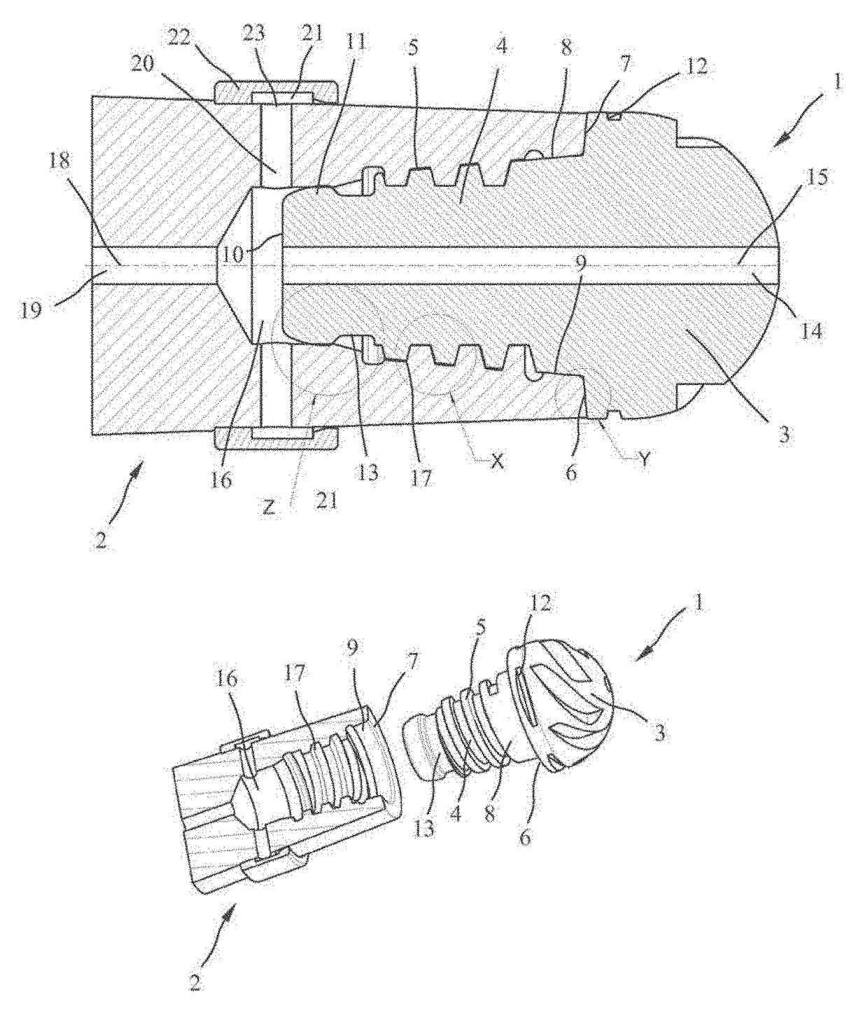
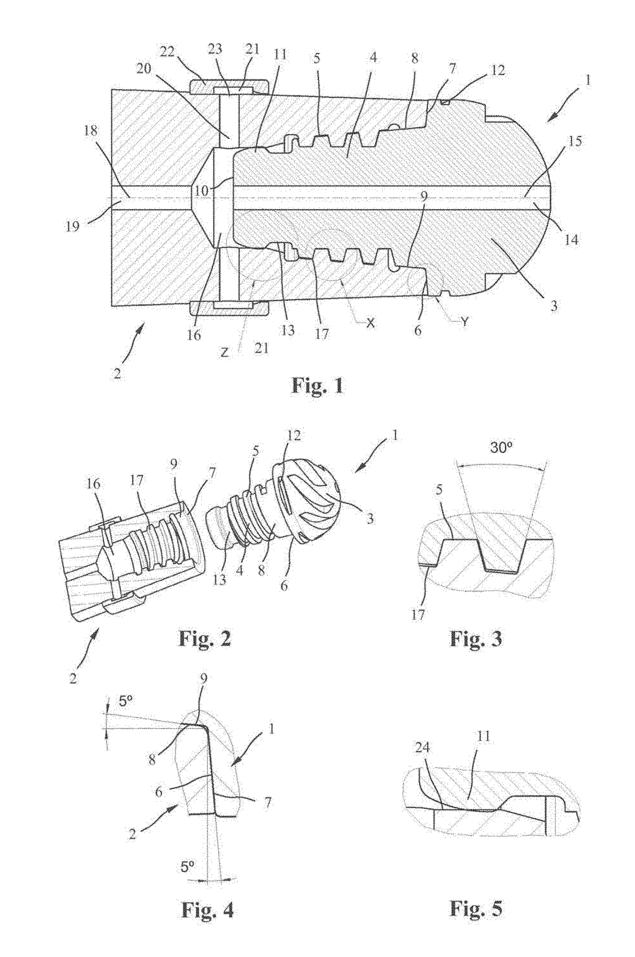
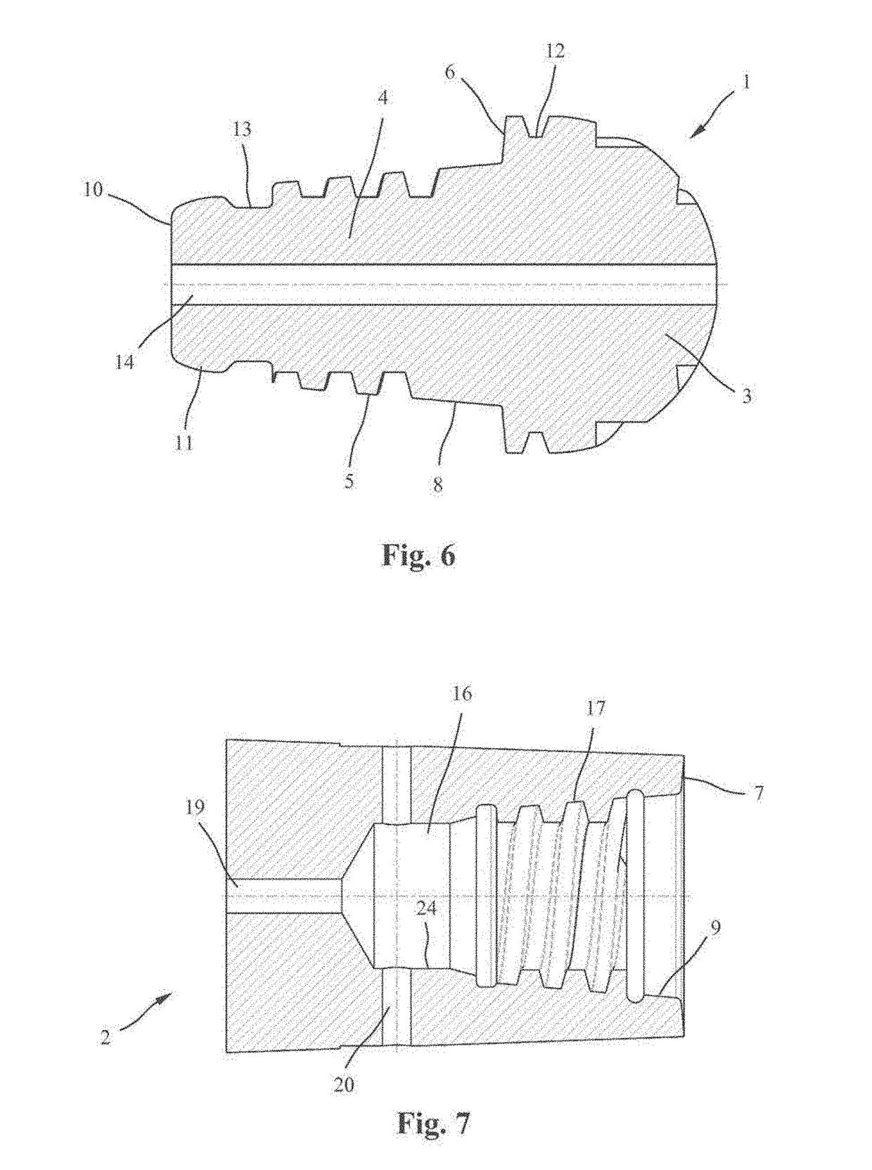
[0028]FIGS. 1 and 2 show a tool arrangement with a screw-in tool 1 and a corresponding tool holder 2 in a longitudinal section and a perspective view. The screw-in tool 1 has a tool head 3, which is designed here as a spherical-head cutter, and a tool shank 4, which tapers conically toward the rear, with an outer winding 5. A first supporting region with a first conical bearing face 6 is provided between the tool head 3 and the outer winding 5 for the placement on a counter-conical contact surface 7 on a front side of the tool holder 2, and a second conical bearing face 8 for the placement on a second conical contact surface 9 in the interior of the tool holder. In this way, a double cone, which ensures an improved centering and an increased supporting effect, is produced on the transition between the tool head 3 and the outer winding 5. A second supporting region 11 is found on a free rear end 10 of the tool shank 4.

[0029]As can be seen particularly from FIG. 2, the tool head 3 has, o


PUM

PropertyMeasurementUnit
Angleaaaaaaaaaa
Angleaaaaaaaaaa
Angleaaaaaaaaaa

Abstract

The invention relates to a screw-in tool (1) and to a tool holder (2) for such a screw-in tool. The screw-in tool (1) contains a tool head (3) and a tool shank (4) having an outer thread (5) and a supporting region arranged between the tool head (3) and the outer thread (5). According to the invention, the supporting region is formed by two conical bearing faces (6, 8) having different cone angles.

Description


Claims


Application Information

Patent Timeline
Owner FRANZ HAIMER MASCHINENBAU KG
Why Eureka
Try Eureka