Lens assembly
a technology of lens and assembly, applied in the field of lenses, can solve the problems of difficulty in meeting the requirements of miniaturization, and achieve the effects of reducing f-number, wide field of view, and shortened total lens length
- Summary
- Abstract
- Description
- Claims
- Application Information
AI Technical Summary
Benefits of technology
Problems solved by technology
Method used
Image

Examples
first embodiment
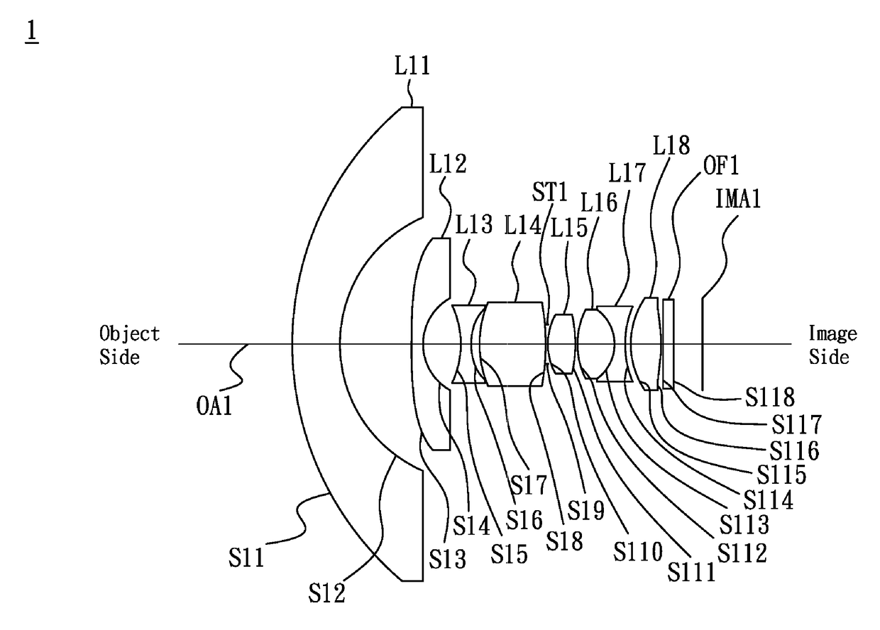
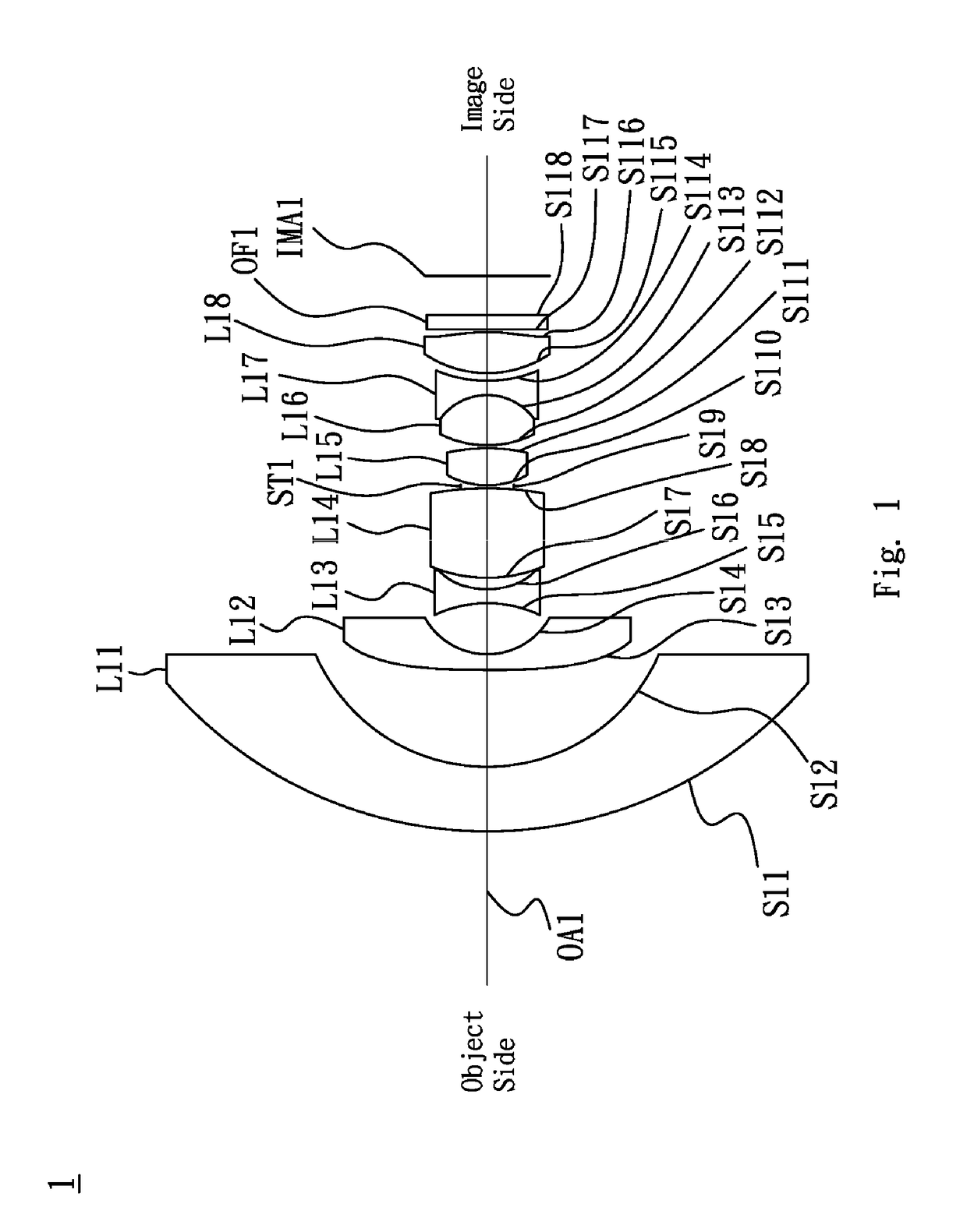
[0033]Referring to FIG. 1, FIG. 1 is a lens layout diagram of a lens assembly in accordance with the invention. The lens assembly 1 includes a first lens L11, a second lens L12, a third lens L13, a fourth lens L14, a stop ST1, a fifth lens L15, a sixth lens L16, a seventh lens L17, an eighth lens L18 and an optical filter OF1, all of which are arranged in order from an object side to an image side along an optical axis OA1. In operation, an image of light rays from the object side is formed at an image plane IMA1.
[0034]The first lens L11 is a meniscus lens with negative refractive power and made of glass material, wherein the object side surface S11 is a convex surface, the image side surface S12 is a concave surface and both of the object side surface S11 and image side surface S12 are spherical surfaces.
[0035]The second lens L12 is a meniscus lens with negative refractive power and made of glass material, wherein the object side surface S13 is a convex surface, the image side surface
second embodiment
[0060]Referring to FIG. 3, FIG. 3 is a lens layout diagram of a lens assembly in accordance with the invention. The lens assembly 2 includes a first lens L21, a second lens L22, a third lens L23, a fourth lens L24, a stop ST2, a fifth lens L25, a sixth lens L26, a seventh lens L27, an eighth lens L28 and an optical filter OF2, all of which are arranged in order from an object side to an image side along an optical axis OA2. In operation, an image of light rays from the object side is formed at an image plane IMA2.
[0061]The first lens L21 is a meniscus lens with negative refractive power and made of glass material, wherein the object side surface S21 is a convex surface, the image side surface S22 is a concave surface and both of the object side surface S21 and image side surface S22 are spherical surfaces.
[0062]The second lens L22 is a meniscus lens with negative refractive power and made of glass material, wherein the object side surface S23 is a convex surface, the image side surface
PUM
| Property | Measurement | Unit |
|---|---|---|
| Length | aaaaa | aaaaa |
| Length | aaaaa | aaaaa |
| Length | aaaaa | aaaaa |
Abstract
Description
Claims
Application Information
 - R&D Engineer
- R&D Manager
- IP Professional
- Industry Leading Data Capabilities
- Powerful AI technology
- Patent DNA Extraction
Browse by: Latest US Patents, China's latest patents, Technical Efficacy Thesaurus, Application Domain, Technology Topic.
© 2024 PatSnap. All rights reserved.Legal|Privacy policy|Modern Slavery Act Transparency Statement|Sitemap