Sliding panel comprising several wall elements that can be displaced laterally

A technology of lateral movement and door unit, applied in the field of sliding walls, to achieve the effect of reducing load and improving running stability

Inactive Publication Date: 2008-03-19
DORMA GMBH & CO KG
View PDF5 Cites 0 Cited by
  • Summary
  • Abstract
  • Description
  • Claims
  • Application Information

AI Technical Summary

Problems solved by technology

[0008] In such sliding walls it is only possi

Method used


Image

  • Sliding panel comprising several wall elements that can be displaced laterally
  • Sliding panel comprising several wall elements that can be displaced laterally
  • Sliding panel comprising several wall elements that can be displaced laterally

Examples


Embodiment Construction

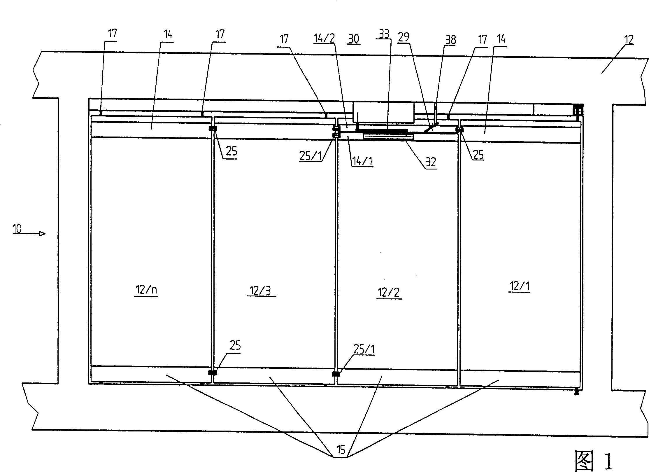
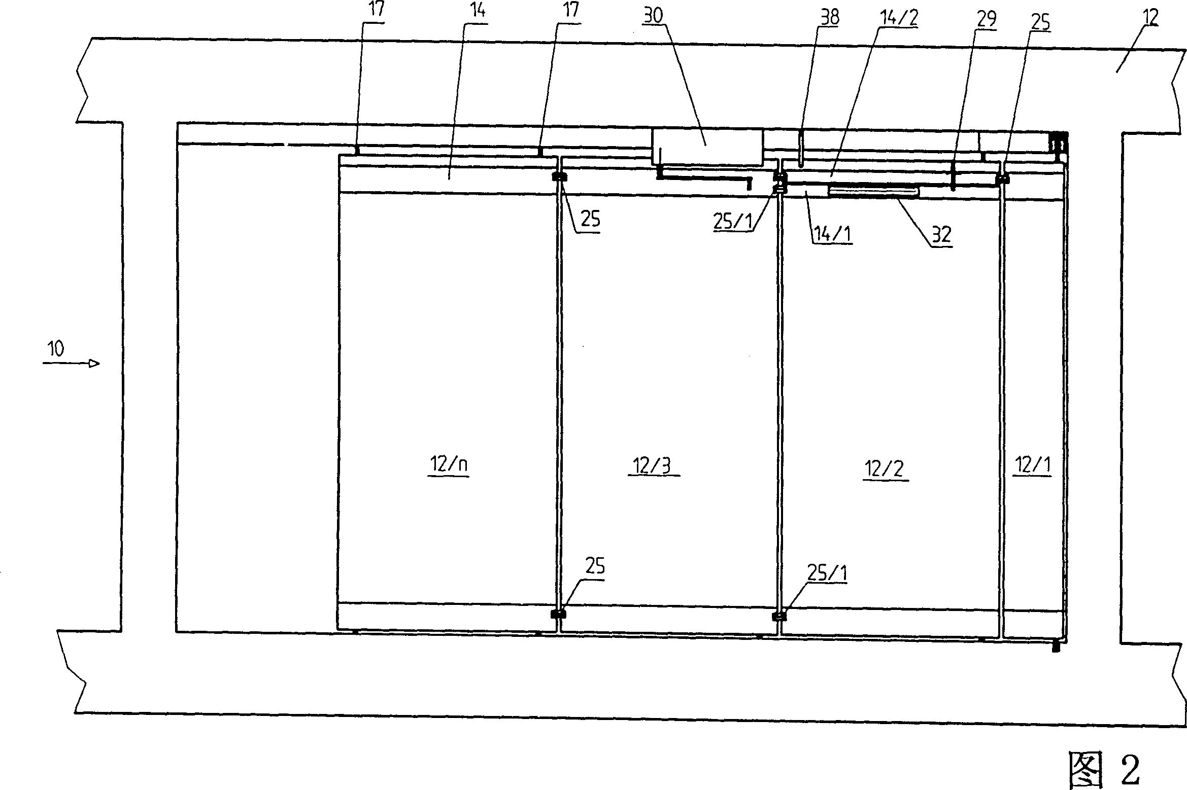
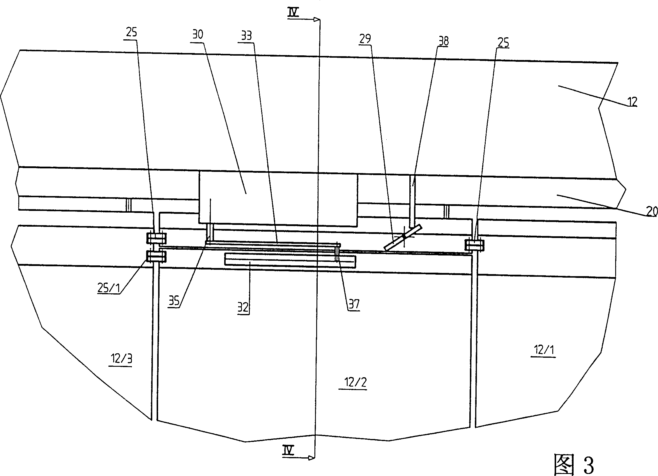
[0024] As shown in FIGS. 1 and 2 , the sliding wall 10 includes a plurality of wall units 12 / 1 to 12 / n which are arranged laterally movably. The upper edge of each of them comprises a load-bearing profile 14 and the lower edge of which comprises a covering profile 15 , both of which are now designed as fully glazed parts. The load-bearing profile 14 has a plurality of load-bearing bolts 17, through which each wall unit 12 / 1 to 12 / n is height-adjustably connected to a drive carriage 23 guided on a slide rail 20 by means of rollers 21 and guide wheels 22. connect. Each drive carriage has a drive motor (not shown here), by means of which each wall unit can be moved along the slide rail. The slide rail 20 is fixedly connected to the building on the ceiling of the space to be partitioned off by means of the sliding wall. It is also possible to connect the individual wall units 12 / 1 to 12 / n to each other and to move them by means of a drive.

[0025] The building


PUM


Abstract

A movable partition system with a plurality of wall elements that are suspended from a guide rail and can be laterally moved to form a wall to close a space in a building. One of the wall elements is realized in the form of a door that can be operatively connected to a door closer that is mounted in a stationary manner to the guide rail. When the wall elements are moved to a closed position, the door is engaged with the door closer so as to pivot the door. When the wall elements are moved out of the closed position, the door is disengaged from the door closer. In addition, the door is prevented from pivoting by a rocker arm during movement of the wall elements, which rocker arm is rotated out of the way of the door when the wall elements are in the closed position to permit pivoting of the door.

Description


Claims


Application Information

Patent Timeline
Owner DORMA GMBH & CO KG
Why Eureka
Try Eureka