Adjustable material stirring device

A material arm and shaft technology, applied in the field of adjustable material shifting device, can solve the problems of high cost, complex structure of the material blocking device, troublesome installation, etc., and achieve the effect of convenient operation, simple structure and compact installation

Inactive Publication Date: 2018-03-09
TIANJIN SERI MACHINERY EQUIP
View PDF0 Cites 0 Cited by
  • Summary
  • Abstract
  • Description
  • Claims
  • Application Information

AI Technical Summary

Problems solved by technology

[0003] The present invention aims to solve the technical problems of complex structure, troubleso

Method used


Image

  • Adjustable material stirring device
  • Adjustable material stirring device
  • Adjustable material stirring device

Examples


Embodiment Construction

[0011] In order to further understand the invention content, characteristics and effects of the present invention, the following examples are given, and detailed descriptions are as follows in conjunction with the accompanying drawings:

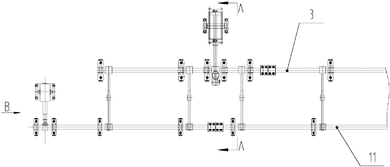
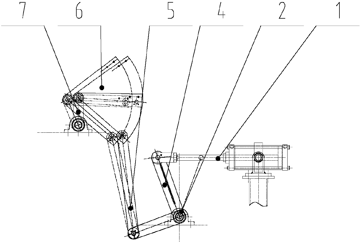
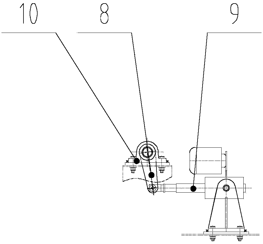
[0012] see Figure 1-Figure 3 , an adjustable material shifting device, characterized in that it includes a frame, a cylinder 1, a first bearing seat 2, a first rotating shaft 3, a single-section swing rod 4, a double-section swing rod 5, a material-setting arm 6, and an adjustment swing arm 7. Push rod swing arm 8, electric push rod 9, second bearing seat 10 and second rotating shaft 11.

[0013] The first bearing seat 2 is installed on the frame, and the first rotating shaft 3 is installed on the first bearing seat 2 .

[0014] The cylinder 1 includes a cylinder body and a telescopic piston rod, the cylinder body 1 is mounted on the frame through a first pin shaft, the axis of the first pin shaft is parallel to the first rotating shaft 3, and


PUM


Abstract

The invention relates to an adjustable material shifting device, which is characterized in that it includes a frame, a cylinder, a first bearing seat, a first rotating shaft, a single-section swing rod, a double-section swing rod, a material shifting arm, an adjusting swing arm, and a push rod swing arm, electric push rod, second bearing seat and second rotating shaft; the cylinder includes a cylinder body and a telescopic piston rod, and the telescopic piston rod of the cylinder is connected to the first rotating shaft through a single-section swing rod; one end of the double-section swing rod is connected to the first rotating shaft , the other end of the double-section swing rod is hinged with the shifting arm; one end of the shifting arm is hinged with the double-section swing rod through the third pin shaft, and the other end of the shifting arm is connected with the adjustment swing arm; one end of the adjustment swing arm is connected with the shifter The other end of the adjustable swing arm is fixed on the second shaft; the body of the electric push rod is installed on the frame through the fourth pin; one end of the push rod swing arm is hinged with the telescopic push rod of the electric push rod, and the push rod swings The other end of the arm is connected with the second rotating shaft. The invention is simple in structure, compact in installation, convenient in operation, economical and practical, and has the effect of improving the production rhythm.

Description


Claims


Application Information

Patent Timeline
Owner TIANJIN SERI MACHINERY EQUIP
Why Eureka
Try Eureka