Refrigeration device
A refrigeration device and refrigerant technology, applied in refrigerators, refrigeration components, refrigeration and liquefaction, etc., can solve problems such as compressor damage, refrigeration machine oil shortage, and reduction of refrigerant circulation in the refrigerant circuit
- Summary
- Abstract
- Description
- Claims
- Application Information
AI Technical Summary
Benefits of technology
Problems solved by technology
Method used
Image

Examples
Embodiment 1
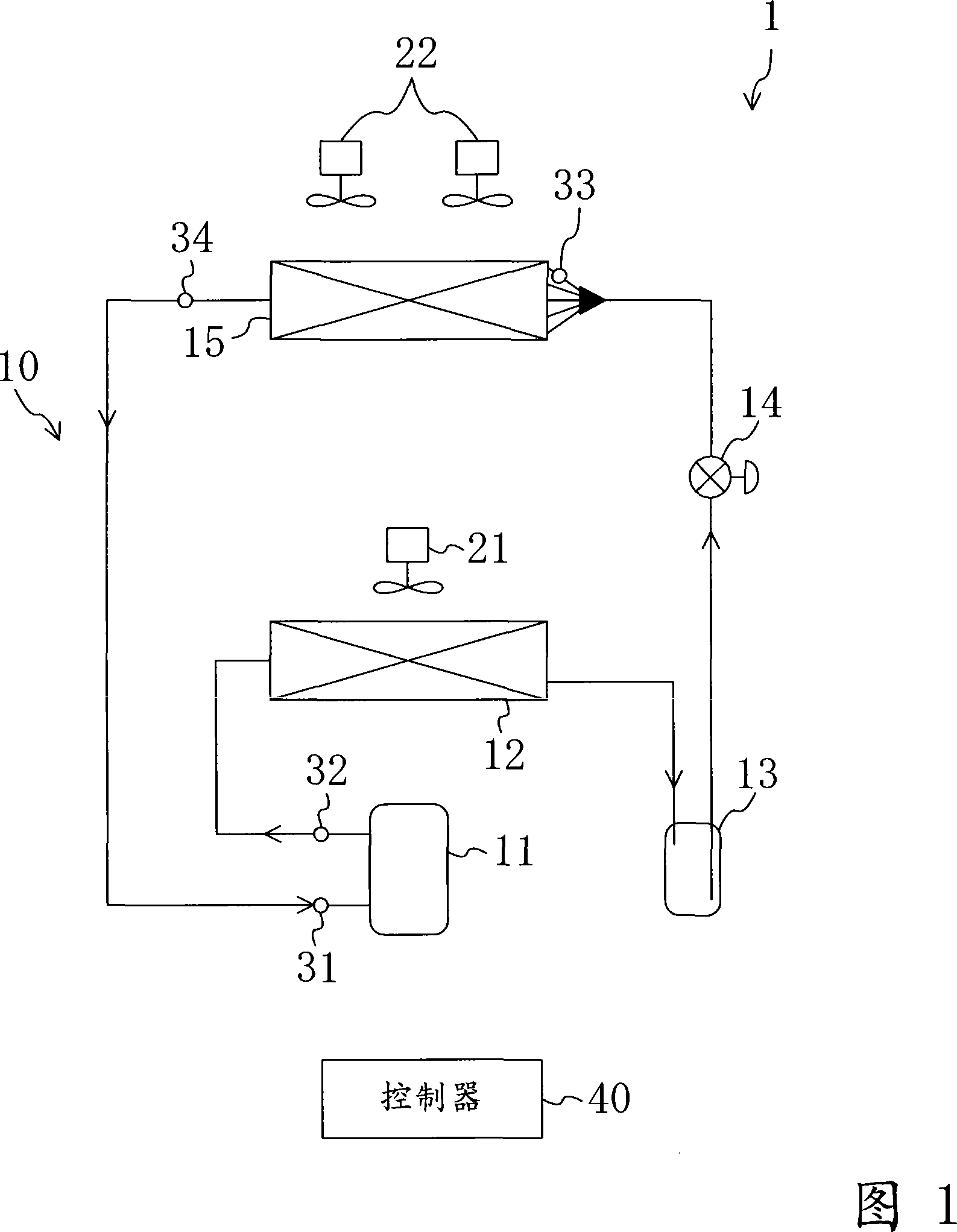
[0036] In the refrigerant circuit 10, as main components, a compressor 11, a condenser 12, an accumulator 13, an electronic expansion valve 14, and an evaporator 15 are connected in this order.
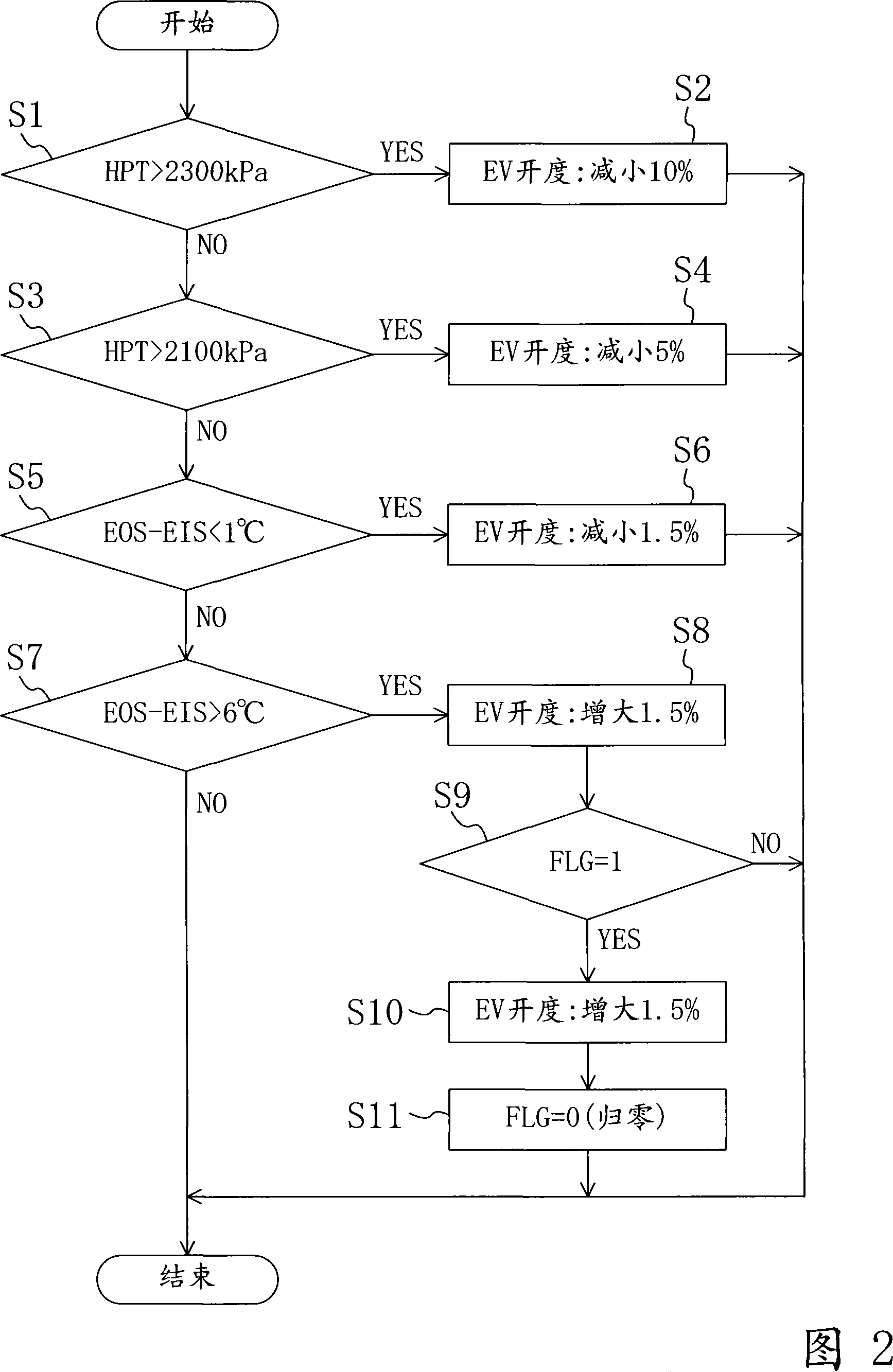
[0037] The above-mentioned compressor 11 is constituted by a fixed-capacity scroll compressor. The above-mentioned condenser 12 is arranged outside the warehouse. A condenser fan 21 that sends outdoor air to the condenser 12 is installed in the vicinity of the condenser 12. In the condenser 12, the outside air sent by the condenser fan 21 exchanges heat with the refrigerant. The accumulator 13 is a cylindrical sealed container and is configured to be able to store excess liquid refrigerant at the bottom. The opening degree of the aforementioned electronic expansion valve 14 can be adjusted. The opening degree of the electronic expansion valve 14 is adjusted in accordance with the degree of superheat of the evaporator 15 and the refrigerant pressure on the high-pressure side of the refriger
Embodiment 2
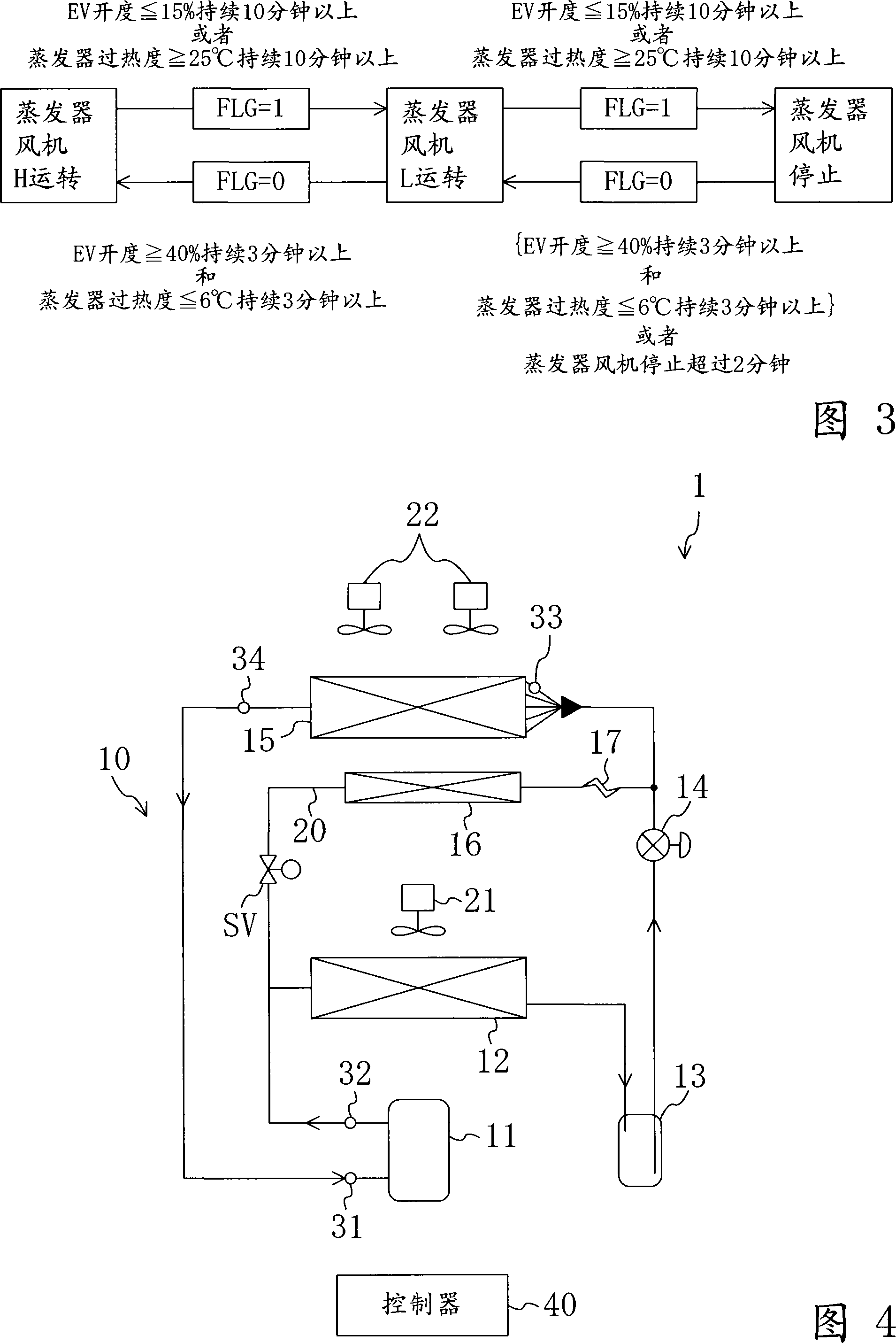
The refrigerating device 1 of the second embodiment can adjust the humidity of the air in the container while cooling the inside of the container.
[0057] As shown in FIG. 4, a bypass pipe 20 is provided in the refrigerant circuit 10. One end of the bypass pipe 20 is connected between the discharge side of the compressor 11 and the inflow side of the condenser 12. The other end is connected between the electronic expansion valve 14 and the inflow side of the evaporator 15. A solenoid valve (SV), a reheater 16, and a capillary tube 17 (capillary tube) are sequentially connected to the bypass pipe 20 in order from the inflow side to the outflow side.
[0058] The above-mentioned reheater 16 is installed in a container warehouse where the evaporator 15 is arranged, and is configured such that the air in the warehouse flowing out from the evaporator 15 passes through the reheater 16. The reheater 16 constitutes a heating heat exchanger for reheating the room air cooled in the evaporato
PUM
 Abstract
Description
Claims
Application Information
 - R&D Engineer
- R&D Manager
- IP Professional
- Industry Leading Data Capabilities
- Powerful AI technology
- Patent DNA Extraction
Browse by: Latest US Patents, China's latest patents, Technical Efficacy Thesaurus, Application Domain, Technology Topic.
© 2024 PatSnap. All rights reserved.Legal|Privacy policy|Modern Slavery Act Transparency Statement|Sitemap