Centrifugal fan with volute

A technology of centrifugal fan and volute, which is applied in the direction of mechanical equipment, machine/engine, liquid fuel engine, etc., which can solve the problems of unsmooth air flow, improve fluency, smooth and smooth connection of molded lines, and reduce left and right dimensions Effect

Pending Publication Date: 2020-03-03
NINGBO FOTILE KITCHEN WARE CO LTD
View PDF3 Cites 0 Cited by
  • Summary
  • Abstract
  • Description
  • Claims
  • Application Information

AI Technical Summary

Problems solved by technology

The profiled lines of the centrifugal fan volute further reduce the left and right dimensions of the volute, improve the airflow collection inside the volute, and reduce the airflow resistance inside the volute, but the tangent line D

Method used


Image

  • Centrifugal fan with volute
  • Centrifugal fan with volute
  • Centrifugal fan with volute

Examples


Embodiment 2

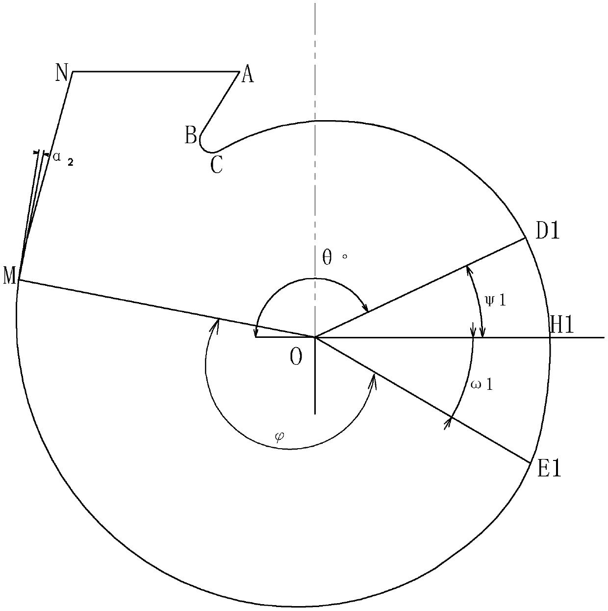
[0037] like image 3 Shown is the second preferred embodiment of the present invention. The difference between this embodiment and the above-mentioned embodiment is only: through the Bezier curve D 1 E.1 A section of logarithmic helix in the prior art is replaced, so as to reduce the left and right dimensions of the volute while increasing the fluency of the airflow.

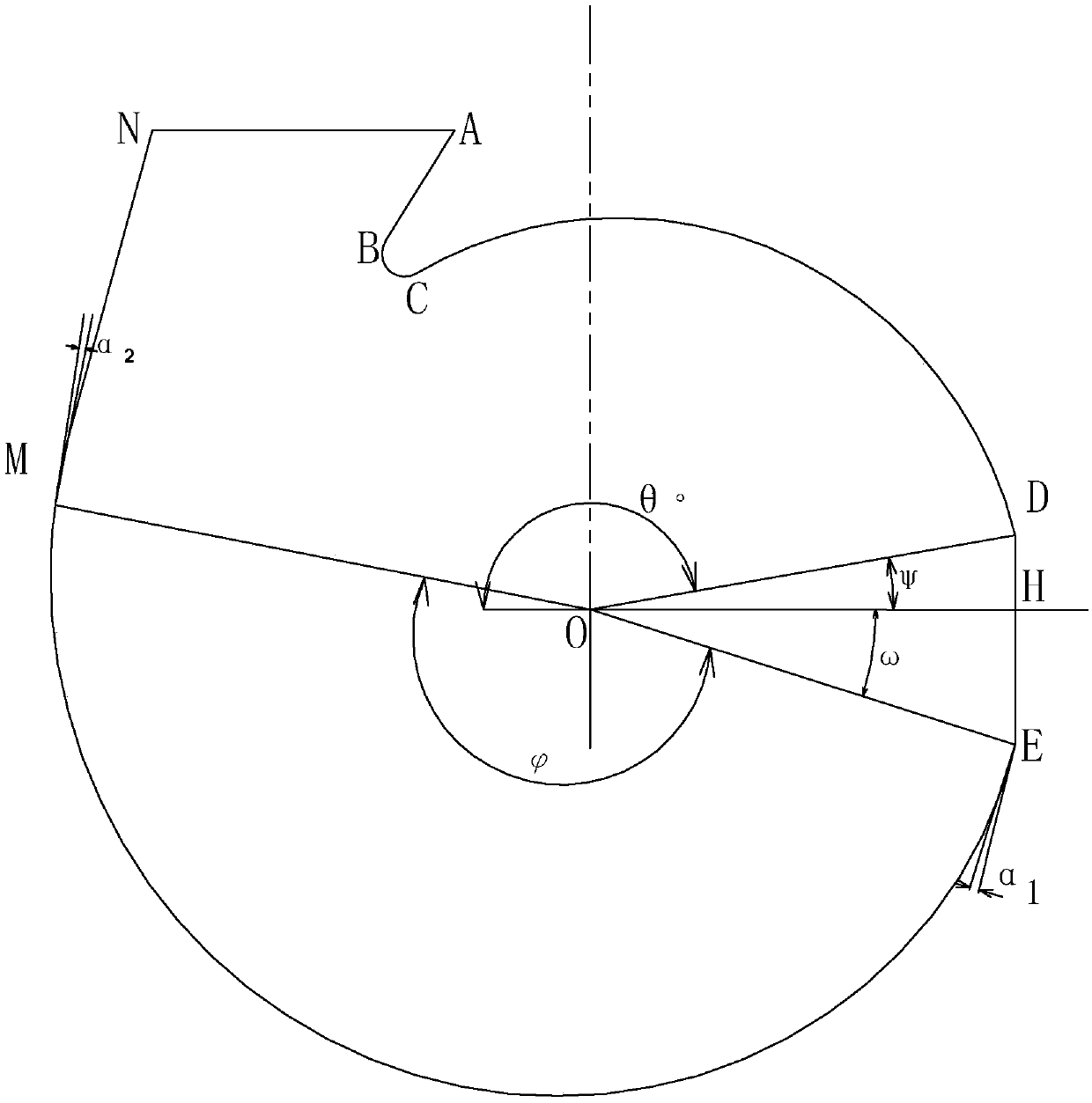
[0038] like Figure 4 As shown, it is the volute type wire of the prior art in this embodiment, and the first helix CD and the second helix DM are sequentially arranged between the start line AC and the end line MN of the volute type wire , the first helix CD is an equiangular helix with a constant expansion angle, the second helix DM is a variable-angle helix with a tapered expansion angle, and the intersection point between the second helix DM and the horizontal line passing through the center O of the volute is H ', the second helix DM is cut, the cut is DE, and the intersection point of the cut DE with the h


PUM


Abstract

The invention relates to a centrifugal fan with a volute. The centrifugal fan comprises the volute, a volute type line comprises a first spiral line CD1, a second spiral line E1M and a Bezier curve D1E1, the Bezier curve D1E1 is disposed between the first spiral line CD1 and the second spiral line E1M, the first spiral line CD1 is an equiangular spiral line with a constant expansion angle, the second spiral line E1M is a variable-angle spiral line tapering at the expansion angle, and a point D1 and a point E1 of the curve D1E1 are respectively located on the upper side and the lower side of ahorizontal line OH1 passing through a volute center O, the point H1 is a control point used for controlling the bending direction of the curve D1E1, and the control point H1 is located on the curve D1E1. On the one hand, the left and right sizes of the volute are reduced, the smoothness of airflow collection and passing inside the volute is improved, the static pressure of the maximum static pressure and the effective air volume section is improved, the large volute effect is achieved at a small size, and pneumatic noise is reduced; and on the other hand, the Bezier curve is adopted for transition, so that the type line connection is smoother, the separation loss caused by the curvature mutation is reduced, and the aerodynamic noise caused by vortex is reduced.

Description


Claims


Application Information

Patent Timeline
Owner NINGBO FOTILE KITCHEN WARE CO LTD
Why Eureka
Try Eureka