Plate type solar hollow heat collection strip

A kind of solar energy and flat-panel technology, applied in the direction of solar thermal power generation, solar thermal devices, heating devices, etc., can solve the problems of complicated process, high production cost, increased difficulty of vacuum process and sealing structure, etc., to simplify the process link and reduce the production cost cost effect

Inactive Publication Date: 2008-09-03
张斌
View PDF0 Cites 3 Cited by
  • Summary
  • Abstract
  • Description
  • Claims
  • Application Information

AI Technical Summary

Problems solved by technology

[0002] The existing solar heat collection strip is a vacuum flat heat collection strip. This kind of heat collection strip usually uses a vacuum heat pipe to be placed in a double-layer vacuum glass interlayer, and the vacuum heat pipe is placed on the condensation end outside the glass plate. Release heat to heat the cold water, and then heat the water in the solar water tank through the thermal cycle between the upper circulation pipe and the lower circulation pipe. This kind of solar vacuum flat heat collection str

Method used


Image

  • Plate type solar hollow heat collection strip
  • Plate type solar hollow heat collection strip
  • Plate type solar hollow heat collection strip

Examples


Embodiment Construction

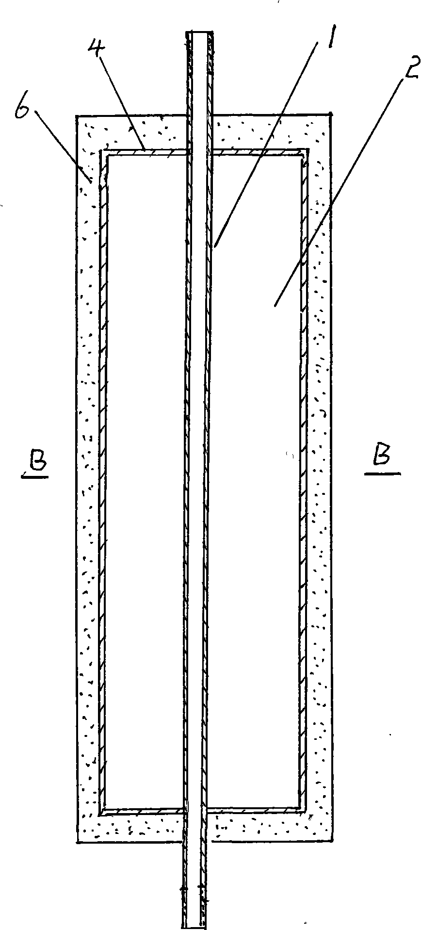
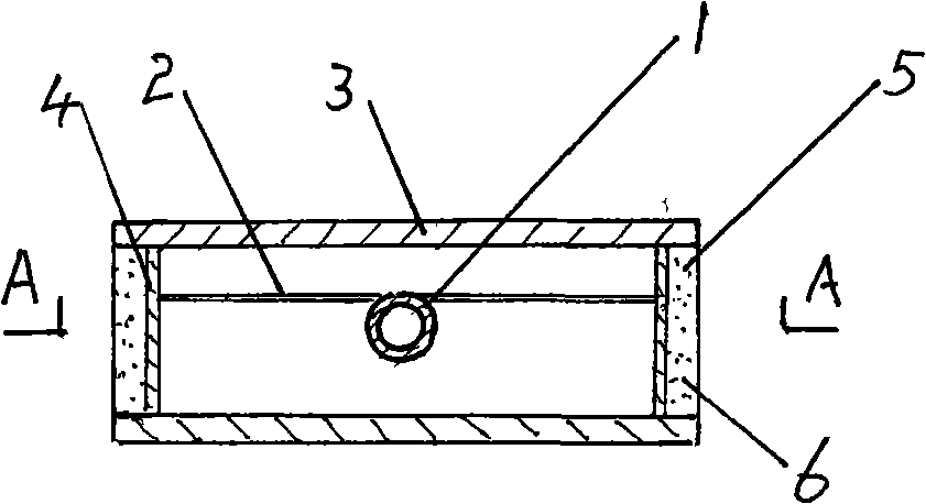
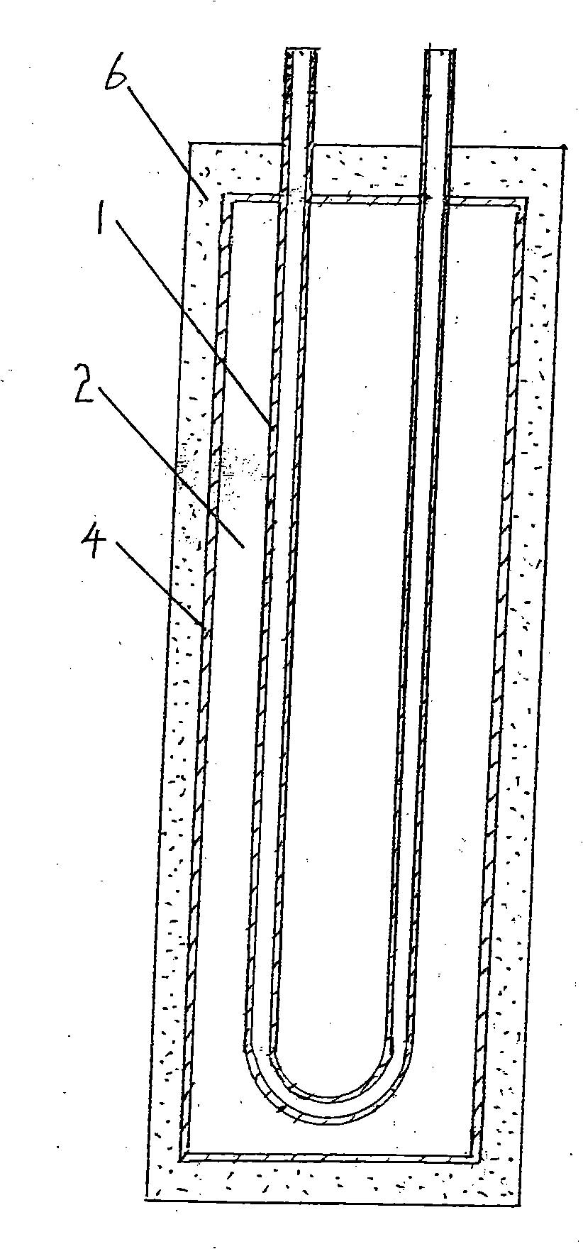
[0013] As shown in Fig. 1, Fig. 2, the present invention is made up of heat collecting tube 1, fin 2 and cover plate 3, it is characterized in that, the panel of cover plate 3 and the back plate are two tempered glass plates; Between the panel and the back plate The cavity is set to be hollow, and inert gas is filled in the hollow cavity to enhance its thermal insulation performance; spacers 4 are arranged around the fins 2 between the panel and the back plate; the spacer 4 is connected with the panel and the back plate A groove 5 is formed between them; a heat insulating layer 6 is filled on the groove 5 around the periphery of the heat collecting strip, and the material of the heat insulating layer is polyurethane; connecting threads 7 are provided on both ends of the heat collecting tube 1 . According to the Fig. 1 structure of the heat collecting tube, the present invention is connected with the solar energy, and the two ends of the heat collecting tube can be respectively co


PUM


Abstract

A flat type solar energy hollow heat collection band is provided. A panel and a back plate of a cover plate (3) are provided with two steel glass plates; the cavity between the panel and the back plate is hollow and is filled with inert gas; spaced stickers (4) are disposed around fins (2) at the periphery between the panel and the back plate; a concave groove (5) is formed between the spacing stickers, and the panel and the back plate; and a heat insulation layer (6) is filled on the concave groove around the periphery of the heat collection band. Shortcomings of vacuum plat type heat collection band are overcome, and simple production technique, a low production cost and good sealing property are provided.

Description


Claims


Application Information

Patent Timeline
Owner 张斌
Why Eureka
Try Eureka