Method for indicating values of corrector and device thereof
A technology of instruments and correction functions, applied in the direction of instruments, etc., can solve problems such as inability to provide indication error and inability to correct instrument indication values
- Summary
- Abstract
- Description
- Claims
- Application Information
AI Technical Summary
Benefits of technology
Problems solved by technology
Method used
Image

Examples
Embodiment 1
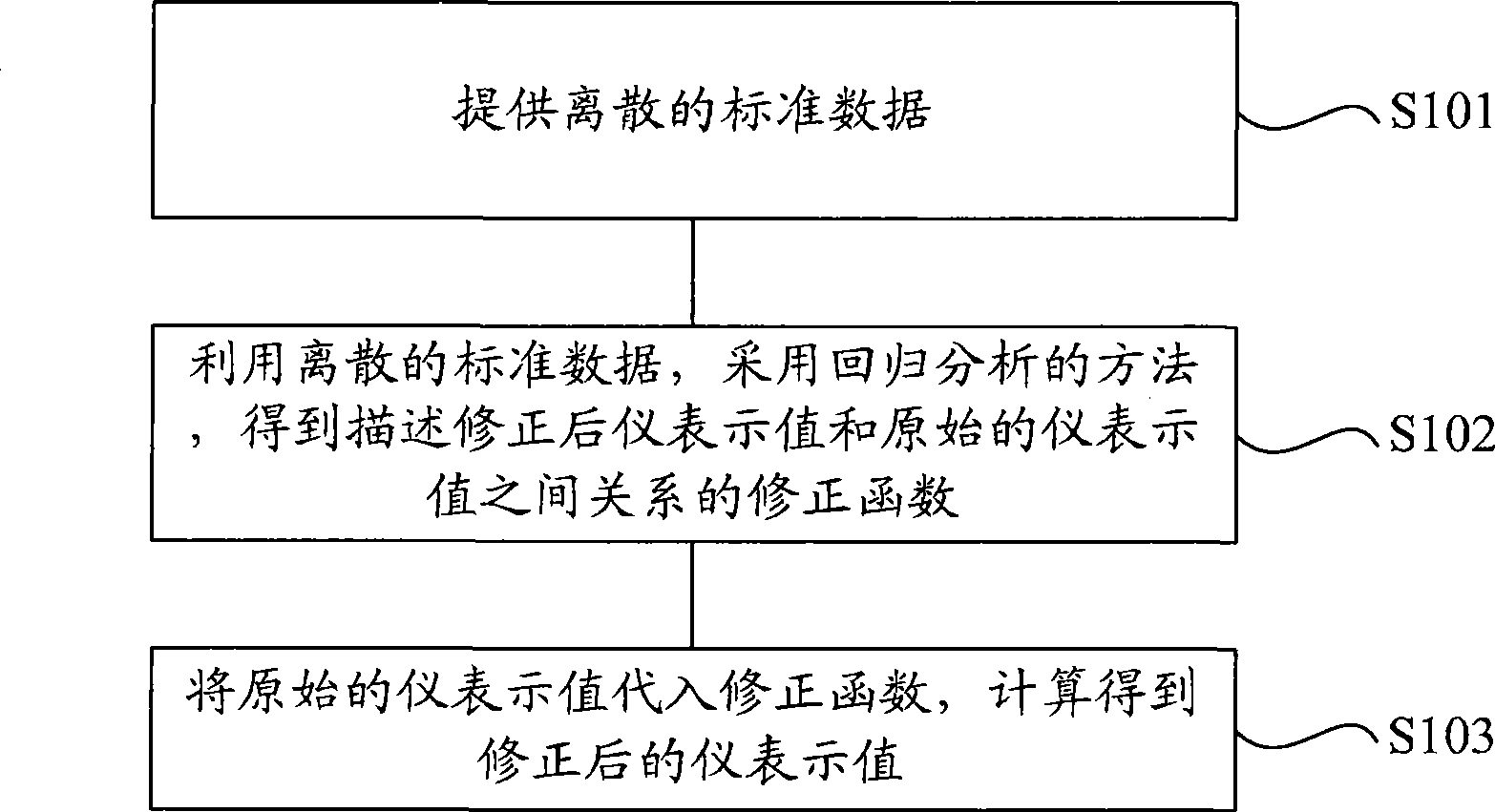
[0074] What is described in this embodiment is a method for correcting the indicated value of a thermometer, and the indicated value of a thermometer between 15°C and 30°C is corrected.
[0075] First, the correction coefficients a and b are calculated using the results obtained by point-by-point calibration of the thermometer. The results obtained by the point-by-point calibration method are listed in Table 1.
[0076] A pair of thermometers of the embodiment of table 1 adopts the result obtained by the method of point-by-point calibration
[0077] Accurate value (y i ) 15.0℃ 20.0℃ 30.0℃ Instrument representation value (x i ) 15.4℃ 20.2℃ 29.8℃
[0078] According to the formulas (1)-(4) in the specific embodiment, it can be calculated: a=-1.04167, b=1.04167.
[0079] Then, the correction coefficients a and b are used to form the correction formula for the indication value of the thermometer:
[0080] y'=-1.04167+1.04167x'
[0081] Then read the orig
Embodiment 2
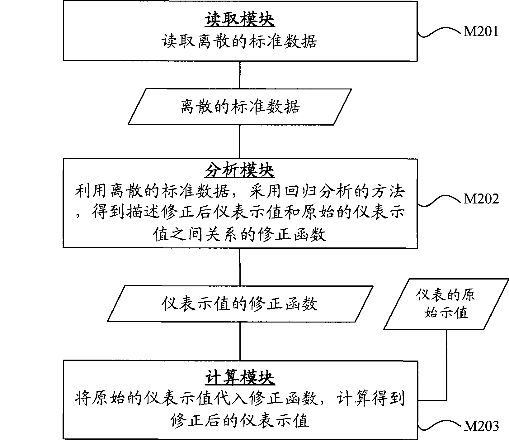
[0084] What is described in this embodiment is a device for correcting the indicated value of a thermometer, which corrects the degree of a thermometer between 15°C and 30°C.
[0085] First, the correction coefficient calculation module is used to calculate the correction coefficients a and b by using the results obtained by point-by-point calibration of the thermometer. The results obtained by the method of point-by-point calibration are shown in Table 1, and the calculation method refers to the content described in Example 1.
[0086] Then use the correction formula to form a module, and use the correction coefficients a and b to form a correction formula for the thermometer indication:
[0087] y'=-1.04167+1.04167x'
[0088] Then use the correction value calculation module to read the original indication value of the thermometer, 24.0°C, and replace x' in the correction formula, and calculate the corrected thermometer indication value of 23.96°C.
[0089] When the original i
Embodiment 3
[0091] What is described in this embodiment is the method for correcting the indicated value of the hygrometer, and the indicated value of a thermometer between 40 and 80 is corrected.
[0092] Firstly, the correction coefficients a and b are calculated using the results obtained by point-by-point calibration of the hygrometer. The results obtained by the point-by-point calibration method are listed in Table 2.
[0093] The results obtained by the method of point-by-point calibration for hygrometer in embodiment three of table 2
[0094] Accurate value (y i %) 40.0 60.0 80.0 The instrument indicates the value ( x i%) 41.0 60.5 80.3
[0095] According to the formulas (1)-(4) in the specific embodiment, it can be calculated: a=-1.67819, b=1.01779.
[0096] Then use the correction coefficients a and b to form the correction formula for the hygrometer indication:
[0097] y'=-1.67819+1.01779x'
[0098] Then read the original indication value of the hygr
PUM
 Abstract
Description
Claims
Application Information
 - R&D Engineer
- R&D Manager
- IP Professional
- Industry Leading Data Capabilities
- Powerful AI technology
- Patent DNA Extraction
Browse by: Latest US Patents, China's latest patents, Technical Efficacy Thesaurus, Application Domain, Technology Topic.
© 2024 PatSnap. All rights reserved.Legal|Privacy policy|Modern Slavery Act Transparency Statement|Sitemap