Oil-gas separating device of cylinder cap

A technology of cylinder head cover and separation device, which is applied in the direction of engine components, machine/engine, engine lubrication, etc., can solve the problems of high cost, complex production process, engine oil leakage, etc., to improve performance, reduce environmental pollution, The effect of improving emission performance

Inactive Publication Date: 2009-06-24
CHERY AUTOMOBILE CO LTD
View PDF0 Cites 7 Cited by
  • Summary
  • Abstract
  • Description
  • Claims
  • Application Information

AI Technical Summary

Benefits of technology

The technology described in this patented design helps improve fuel efficiency while reducing emissions without adding extra parts like an intake manifold. By separating liquids into different areas within one chamber called the space between them, there are fewer points where they hit each other during operation compared to traditional methods such as direct injection (DI) engines. Additionally, these designs allow gases entering through certain openings on top of the main body of the vehicle to pass downwardly along its way before being collected again inside the system itself. Overall, this new method enhances combustion quality and reduces harmful exhaust fumes produced when burning fossil fuels.

Problems solved by technology

This patented technical problem addressed in this patents relates to improving the efficiency or performance of separating oily liquids from gases by utilizing different types of structures like bags made up of plastic material that can be easily formed without adding extra materials at high costs.

Method used


Image

  • Oil-gas separating device of cylinder cap
  • Oil-gas separating device of cylinder cap
  • Oil-gas separating device of cylinder cap

Examples


Embodiment Construction

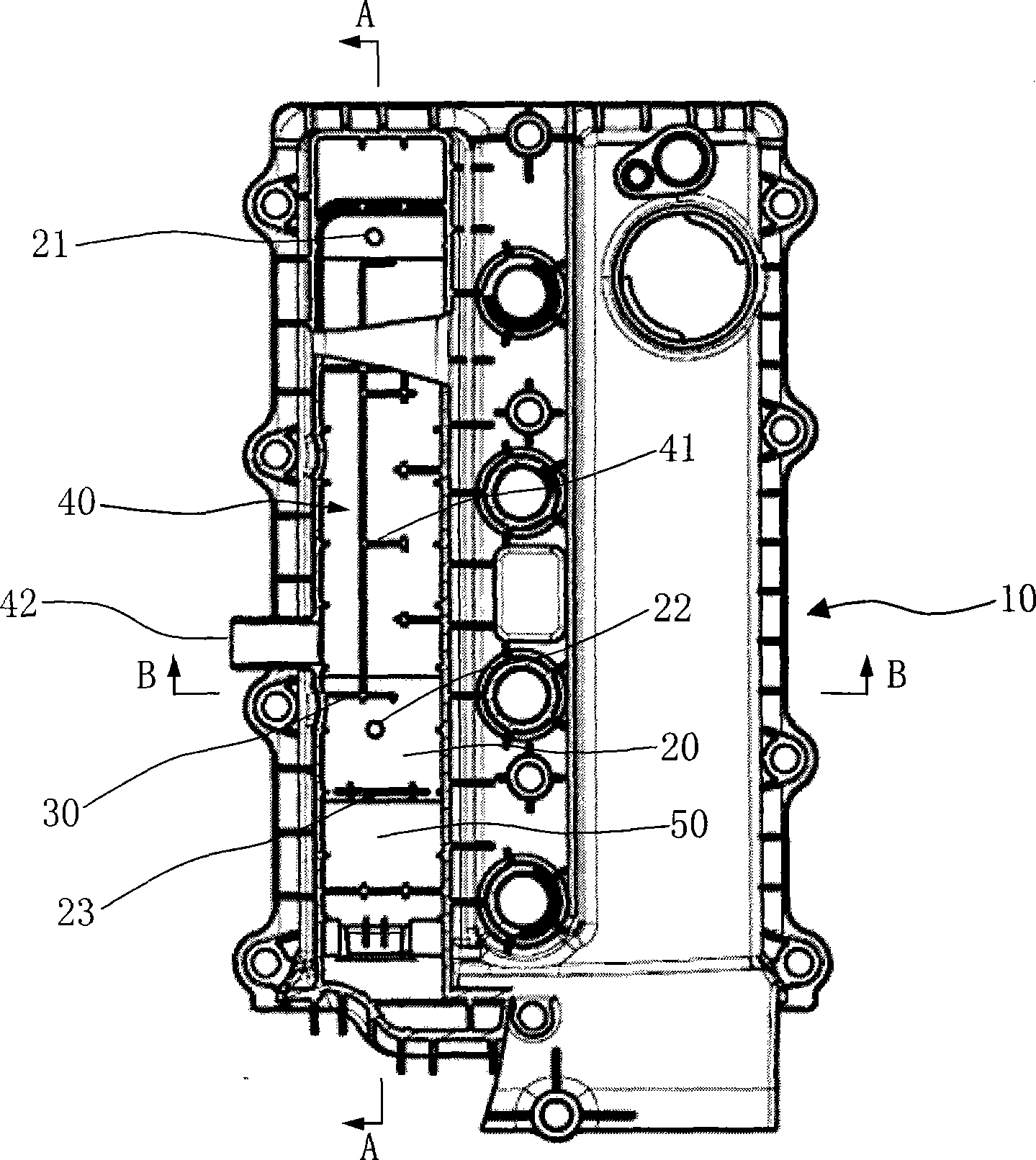
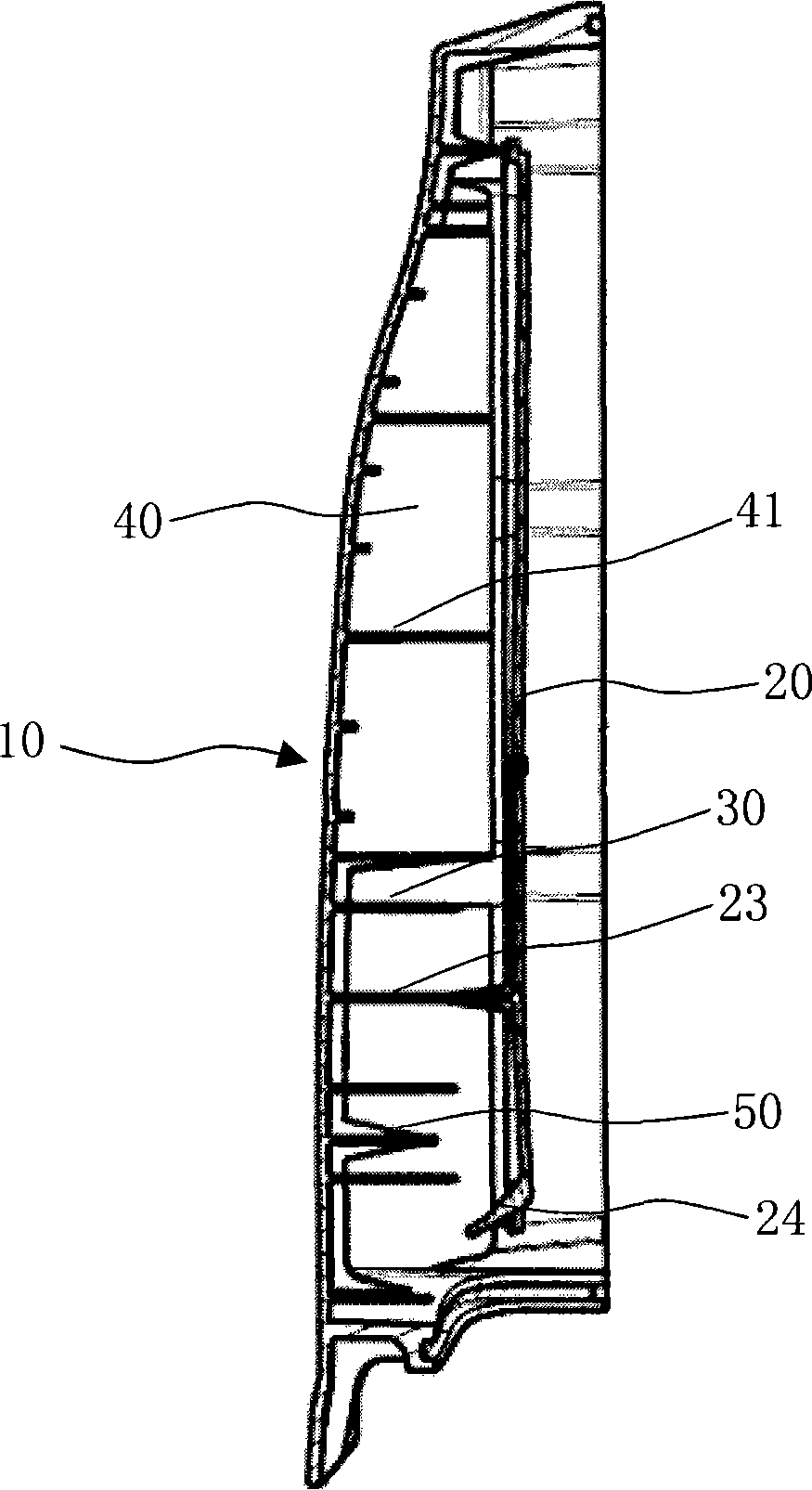
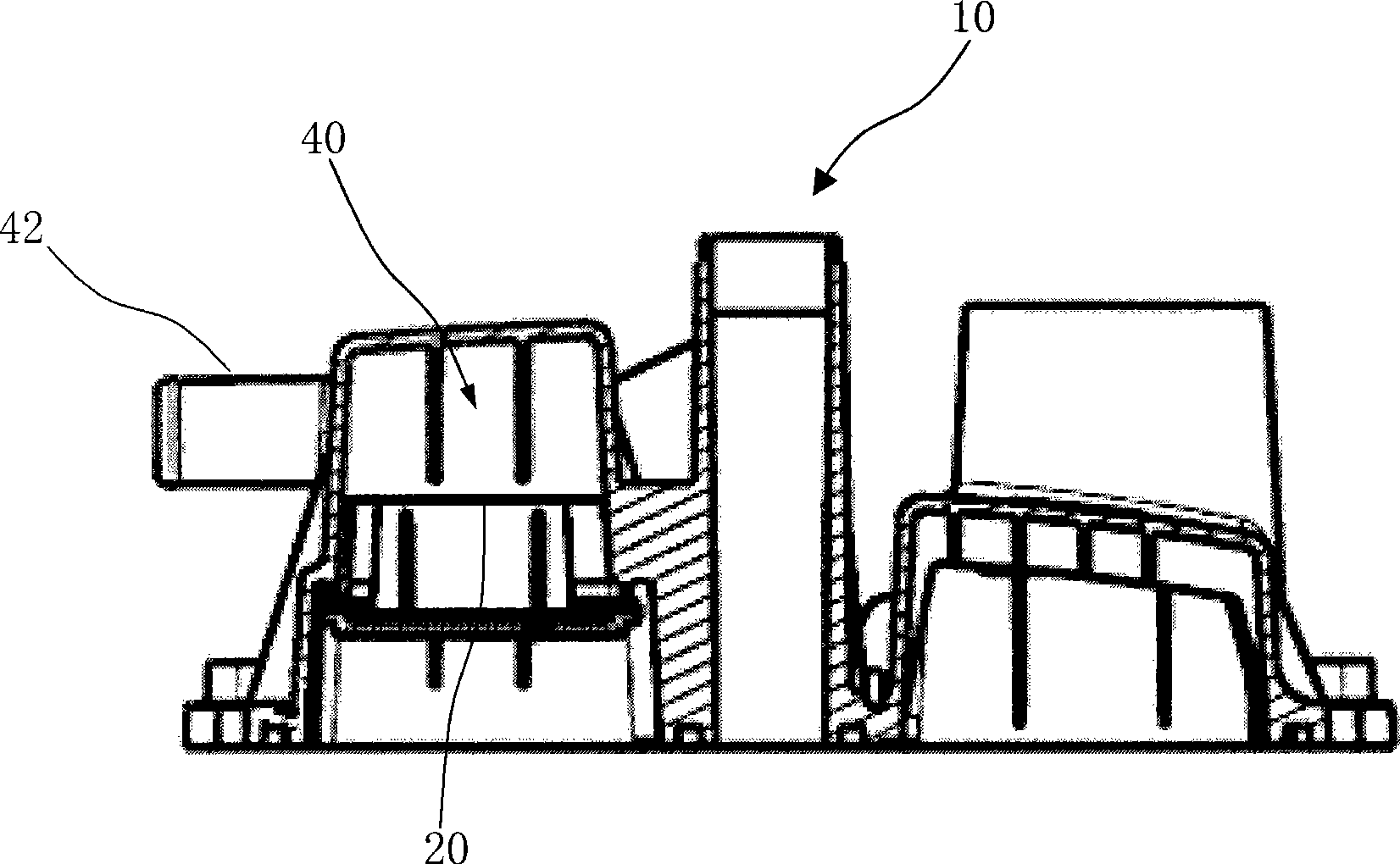
[0010] Such as figure 1 As shown, a cylinder head cover oil-gas separation device is provided with a bottom plate 20 on the lower side of the cylinder head cover 10, a top-to-bottom partition plate 30 is provided between the cylinder head cover 10 and the bottom plate 20, the cylinder cover 10, the bottom plate A cavity 40 is formed between 20 and the partition plate 30 for the circuitous flow of oil and gas. The inlet of the cavity 40 is arranged inside the cylinder cover 10, the outlet is arranged on the cylinder cover 10, and the cavity 40 is arranged along the front cavity of the oil flow direction. There is an oil-gas separation mechanism, the rear cavity is set as a passage, and the bottom plate 20 is provided with a first oil return hole 21.

[0011] When working, the oil and gas flow in from the inlet of the cavity 40, and are first processed by the oil and gas separation mechanism, and then the gas flows back to the passage behind the cavity 40. Since there are no obstacles


PUM


Abstract

The invention belongs to the technical field of automobile engine, in particular to a cylinder head cover gas and oil separating device. The lower side of the cylinder head cover of the invention is provided with a base plate; division plates from top to bottom are arranged between the cylinder head cover and the base plate; empty cavities for circuitous circulation of the gas and oil are formed between the cylinder head cover and base plate and the division plates; an inlet of the empty cavity is arranged inside the cylinder head cover, and an outer thereof is arranged on the cylinder head cover; a front cavity of the empty cavity along the flow direction of the gas and oil is provided with the gas and oil separating mechanism and a back cavity thereof is arranged as an access; the base plate is provided with a first oil return hole. In the invention, the oil and the gas are firstly processed by the gas and separating mechanism in front of the empty cavity, and then the access of the back part of the empty cavity plays a role of slowing air flow, so that oil drops in the air sink during slow flowing to be separated when touching the base plate or side walls. In the invention, the oil and the gas can be separated more thoroughly, thus improving the service performance of the engine, promoting the emission performance of the engine and reducing the environmental pollution.

Description


Claims


Application Information

Patent Timeline
Owner CHERY AUTOMOBILE CO LTD
Why Eureka
Try Eureka