Self-generating sewing machine lamp
A sewing machine and lighting technology, which is applied to sewing machine components, lighting applications, sewing equipment, etc., can solve the problems of complex structure of the transformer device, poor safety of high-voltage electricity, and easy failure, and achieves low use cost, and is not easy to fail. good safety effect
- Summary
- Abstract
- Description
- Claims
- Application Information
AI Technical Summary
Problems solved by technology
Method used
Image

Examples
Embodiment 1
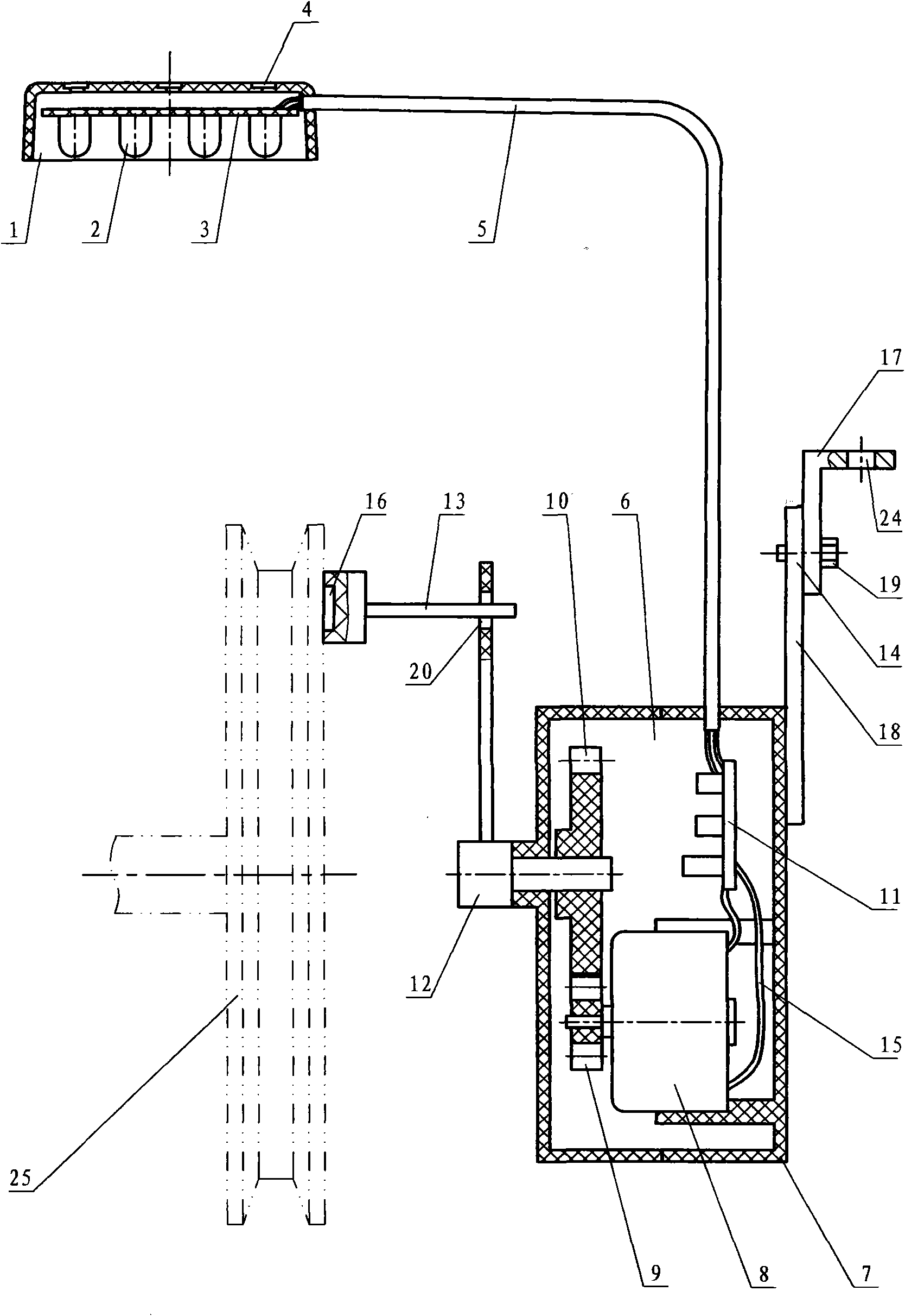
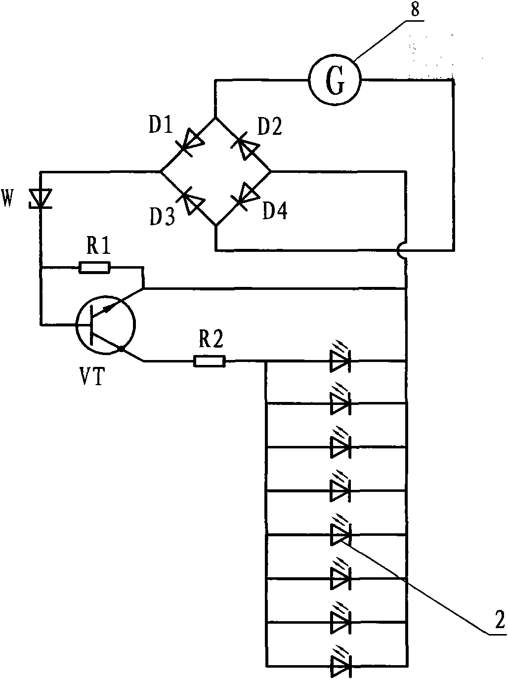
[0015] Combine below Figure 1 to Figure 4 A detailed description will be made to the specific embodiment of the present invention. Embodiment 1: as figure 1 , a self-generating sewing machine lighting lamp, including a lamp housing 1, a circuit board 3 of light-emitting diode groups 2, a magnet 4, and an electric wire 5, the circuit board 3 is arranged in the lamp housing 1, and several light-emitting diode groups 2 are arranged on the circuit board 3 , The magnet 4 is arranged above the lamp housing 1, one end of the electric wire 5 is connected to the LED group 2, and the other end of the electric wire 5 is provided with a power generating device 6. Generating device 6 is made up of shell 7, generator 8, pinion 9, bull gear 10, circuit board 11, pivoting arm 12, driving lever 13, support 14, and generator 8 is located in generating device 6, and pinion 9 is installed on On the extended end of the generator 8, the pinion 9 meshes with the large gear 10, the large gear 10 is c
Embodiment 2
[0017] Embodiment 2: as Figure 4 Compared with Embodiment 1, metal hose 21 and lamp holder 22 are added. The metal hose can adjust the position and angle of the lamp arbitrarily. The bottom of lamp holder 22 is provided with a magnet, which can be directly adsorbed on the sewing machine body. The power generating device 6 is the same as that of Embodiment 1, and will not be described in detail here.
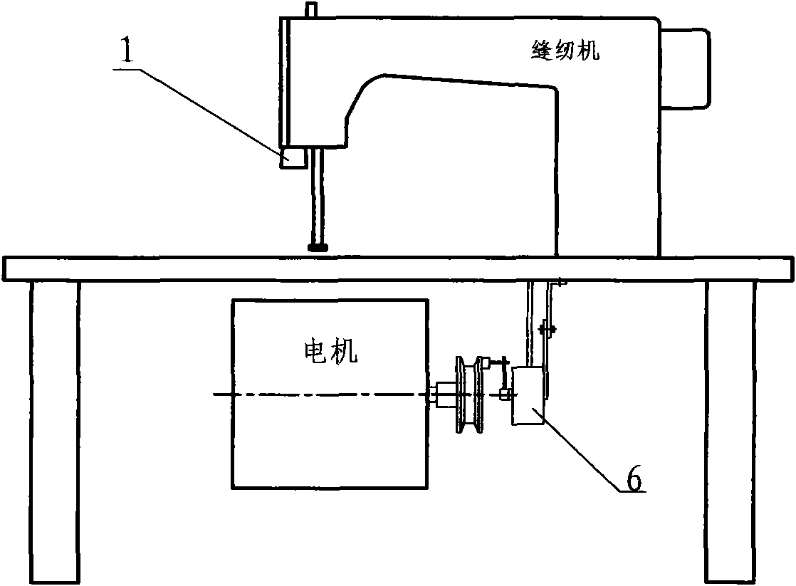
[0018] Generator 6 also can be installed on the flywheel outer surface on the right side above the sewing machine table.
PUM
 Abstract
Description
Claims
Application Information
 - R&D Engineer
- R&D Manager
- IP Professional
- Industry Leading Data Capabilities
- Powerful AI technology
- Patent DNA Extraction
Browse by: Latest US Patents, China's latest patents, Technical Efficacy Thesaurus, Application Domain, Technology Topic.
© 2024 PatSnap. All rights reserved.Legal|Privacy policy|Modern Slavery Act Transparency Statement|Sitemap