Mounting method of fire emergency marker lamp

A technology of fire emergency and installation method, which is applied in the direction of lighting devices, lighting devices, parts of lighting devices, etc., can solve the problems that fire emergency sign lights are not suitable for fire emergency sign lights, etc., and achieve the effect of ensuring human safety and reducing casualties

Inactive Publication Date: 2016-04-20
上海凯玲消防工程有限公司
View PDF5 Cites 0 Cited by
  • Summary
  • Abstract
  • Description
  • Claims
  • Application Information

AI Technical Summary

Benefits of technology

This new technology allows people who have gone fires without being detected through visual means like smoke detectors or lights. They use this sensor to activate an alarm when they see someone else inside their house after having been left unattended at home during these times. Additionally, if one's body falls down accidently while still alive outside, another person will hear them speaking out loud enough to help rescue those trapped within. Overall, this innovation improves security measures against flames caused by human error such as falling off stairs or burning clothes.

Problems solved by technology

The technical problem addressed in this patent text is that existing fire emergency sign lights are not effective in guiding blind individuals during a fire emergency. Blind people cannot see the arrows on the sign lights and therefore cannot determine the escape route without assistance. This poses a serious threat to their safety and can result in casualties. The patent proposes a new fire emergency sign lamp that includes a gravity sensing floor mat and a sounder to help blind individuals know the escape route. The technical problem is to provide a solution that is specifically designed for blind individuals and requires a different installation method compared to existing sign lights.

Method used


Image

  • Mounting method of fire emergency marker lamp
  • Mounting method of fire emergency marker lamp
  • Mounting method of fire emergency marker lamp

Examples


Embodiment 1

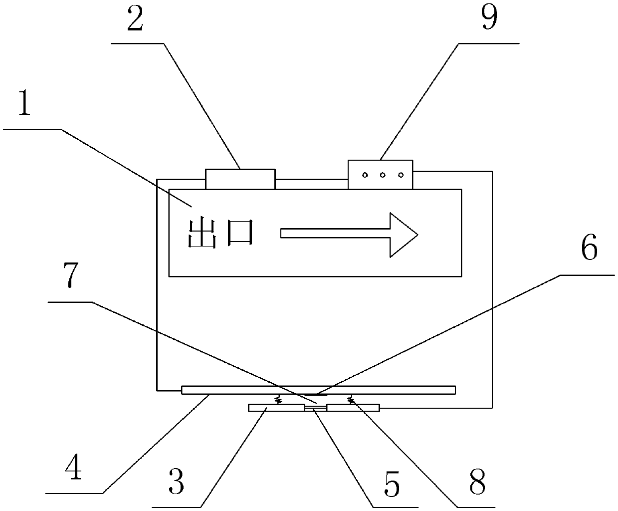
[0022] Such as figure 1 As shown, a fire emergency sign lamp in this embodiment includes a lightweight lamp housing 1, a light bulb installed in the lamp housing 1, a power supply 2 installed on the back of the lamp housing 1, a gravity sensing floor mat and a sound generator 9.

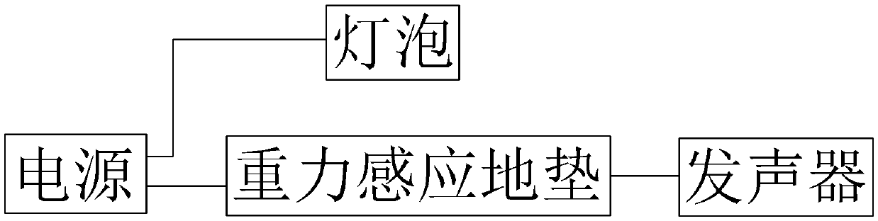
[0023] Such as figure 2 As shown, the power supply 2, the gravity induction floor mat and the sounder 9 are connected by wires in sequence, and the power supply 2 also supplies power to the bulb at the same time.

[0024] Arrows and patterns indicating directions are printed on the lamp housing 1, and the above arrows and patterns are all white, so that the arrows and patterns on the lamp housing 1 can be seen through when the light bulb is turned on.

[0025] The gravity sensing floor mat includes a bottom layer 3, an induction plate 4 and a compression spring 8, the upper surface of the bottom layer 3 is opposite to the lower surface of the induction plate 4, the bottom layer 3 is located below, and

Embodiment 2

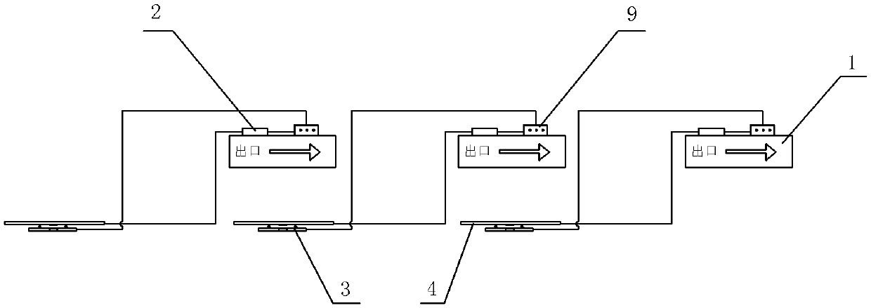
[0038] The difference between this embodiment and Embodiment 1 is that when installing the fire emergency sign lamp, the lamp housing 1 of the second fire emergency sign lamp is located behind the lamp housing 1 of the first fire emergency sign lamp, and the second fire emergency The lamp housing 1 of the emergency marker lamp is flush with the induction plate 4 of the first fire emergency marker lamp.


PUM

PropertyMeasurementUnit
Free lengthaaaaaaaaaa
Elastic coefficientaaaaaaaaaa

Abstract

The invention discloses a mounting method of a fire emergency marker lamp. The mounting method comprises the steps of step I, fixing a lamp shell of the fire emergency marker lamp to the wall surface; step II, laying a gravity sensing ground mat of the fire emergency marker lamp on the ground, with the bottom layer of the gravity sensing ground mat fitting the ground and the gravity sensing ground mat positioned behind the lamp shell of the fire emergency marker lamp; and step III, repeating the step I and the step II to lay a plurality of fire emergency marker lamps along an escape route, with the lamp shells and the gravity sensing ground mats of the adjacent fire emergency marker lamps being flush. The mounting method of the fire emergency marker lamp is matched with a fire emergency marker lamp applied by the inventor on the same day. The fire emergency marker lamp can be utilized for guiding the blind to acquire the escape route, so that the blind can conveniently escape from the fire scene, the personal safety of the blind is guaranteed, and the casualties are reduced.

Description


Claims


Application Information

Patent Timeline
Owner 上海凯玲消防工程有限公司
Why Eureka
Try Eureka