Inflation-free tire
A technology for non-pneumatic tires and tires, which is applied in the direction of non-pneumatic tires, tire parts, transportation and packaging, etc. It can solve the problems that affect the normal use of tires assembled in series with inner tubes, the inner tubes cannot maintain a regular shape, and the processing quality of tires is high. , to achieve the effect of simple structure, suitable compression resistance and elasticity, and low cost
- Summary
- Abstract
- Description
- Claims
- Application Information
AI Technical Summary
Problems solved by technology
Method used
Image


Examples
Embodiment 1
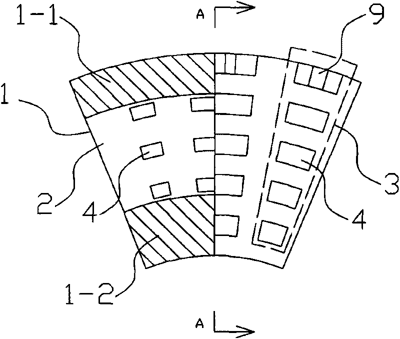
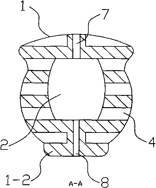
[0028] Example 1 as Figure 1~2 As shown, the non-pneumatic tire includes a ring-shaped tire body 1, the outside of which is a tire crown 1-1, and the inside is a placenta 1-2. The inside of the tire body is provided with an annular inner hole 2 extending in the same direction. The radial section of the inner hole is drum-shaped, and there are multiple deformation groove groups 3 symmetrically along the length direction on both sides of the tire body (indicated by the dotted line box in the figure). Groove 4 is formed, spacer ribs are arranged between adjacent deformation grooves, the annular inner hole communicates with the deformation grooves on both sides, and the top surface of tire crown 1-1 is provided with ventilation holes 7 and concave-convex toe patterns 9 at intervals. The hole radially extends to communicate with the annular inner hole 2, and a positioning installation hole 8 is opened on the bottom surface of the placenta 1-2.
Embodiment 2
[0029] Example 2 as Figure 3-4 As shown, the non-pneumatic tire includes a ring-shaped tire body 1, the outer side of which is a tire crown 1-1, and the inner side is a placenta 1-2. The inside of the tire body is provided with a ring extending in the same direction and having a circular radial section. Shaped inner hole 2, both sides of the tire body are symmetrically provided with plural deformation groove groups 3 along the length direction (indicated by the dotted line box in the figure), and each group of deformation groove groups is composed of 5 parallel deformation grooves 4 located between the crown and the placenta , spacer ribs are provided between adjacent deformation grooves, spacer ribs are also provided between the deformation grooves and the annular inner hole so that the two are independent of each other, and the top surface of the crown 1-1 is provided with air holes 7, and the air holes are radially Extending and communicating with the annular inner hole 2, a
Embodiment 3
[0030] Example 3 as Figure 5-6 As shown, the non-pneumatic tire includes a ring-shaped tire body 1, its outer side is a tire crown 1-1, and its inner side is a placenta 1-2. Shaped inner hole 2, both sides of the tire body are symmetrically provided with plural deformation groove groups 3 along the length direction (indicated by the dotted line box in the figure), and each group of deformation groove groups is composed of 5 parallel deformation grooves 4 located between the crown and the placenta Spacer ribs are provided between adjacent deformation grooves, spacer ribs are provided between the deformation groove 4 and the annular inner hole 2 to make the two independent of each other, and the top surface of the crown 1-1 is provided with vent holes 7 and concave-convex toes The vent hole radially extends to communicate with the annular inner hole 2, and the bottom surface of the placenta 1-2 is provided with a positioning installation hole 8.
PUM
 Abstract
Description
Claims
Application Information
 - R&D Engineer
- R&D Manager
- IP Professional
- Industry Leading Data Capabilities
- Powerful AI technology
- Patent DNA Extraction
Browse by: Latest US Patents, China's latest patents, Technical Efficacy Thesaurus, Application Domain, Technology Topic.
© 2024 PatSnap. All rights reserved.Legal|Privacy policy|Modern Slavery Act Transparency Statement|Sitemap