Guide sleeve removing device in die

A guide sleeve and mold technology, applied in the field of stamping molds, can solve the problems of difficult to remove guide sleeves, guide sleeves falling into, etc.

Inactive Publication Date: 2010-09-29
SUZHOU UIGREEN MICRO & NANO TECH CO LTD
View PDF0 Cites 0 Cited by
  • Summary
  • Abstract
  • Description
  • Claims
  • Application Information

AI Technical Summary

Benefits of technology

This patented technology improves upon previous methods for guiding bushings used during injection molds by adding an improved design with two holes: one on top where there are no longer any problematic parts like this part being stuck or difficult removal from the die plate. Another hole allows compressed gas (usually nitrogen) pressure to pass through it instead of directly hitting these areas causing damage. By doing both ways, the system ensures accurate placement of the new material without damaging other components within the melted plastic injector machine.

Problems solved by technology

This patented describes how to make sure guiding columns have no excessive space or any other issues with their installation.

Method used


Image

  • Guide sleeve removing device in die
  • Guide sleeve removing device in die
  • Guide sleeve removing device in die

Examples


Embodiment Construction

[0012] Hereinafter, the present invention will be described in detail with reference to the drawings.

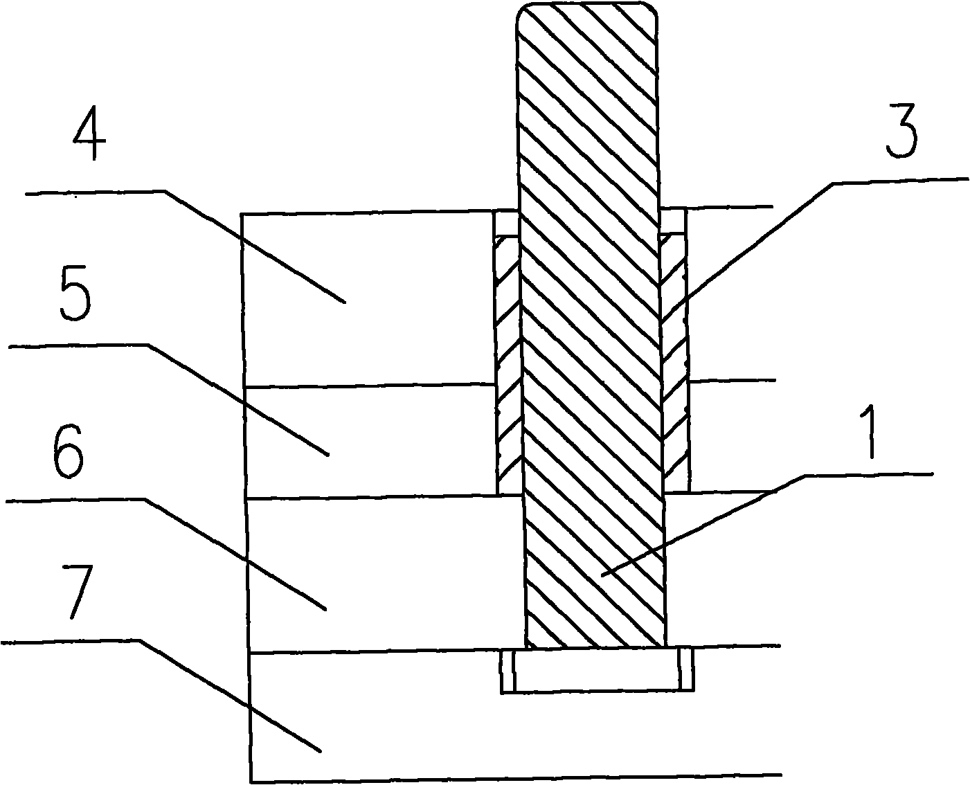
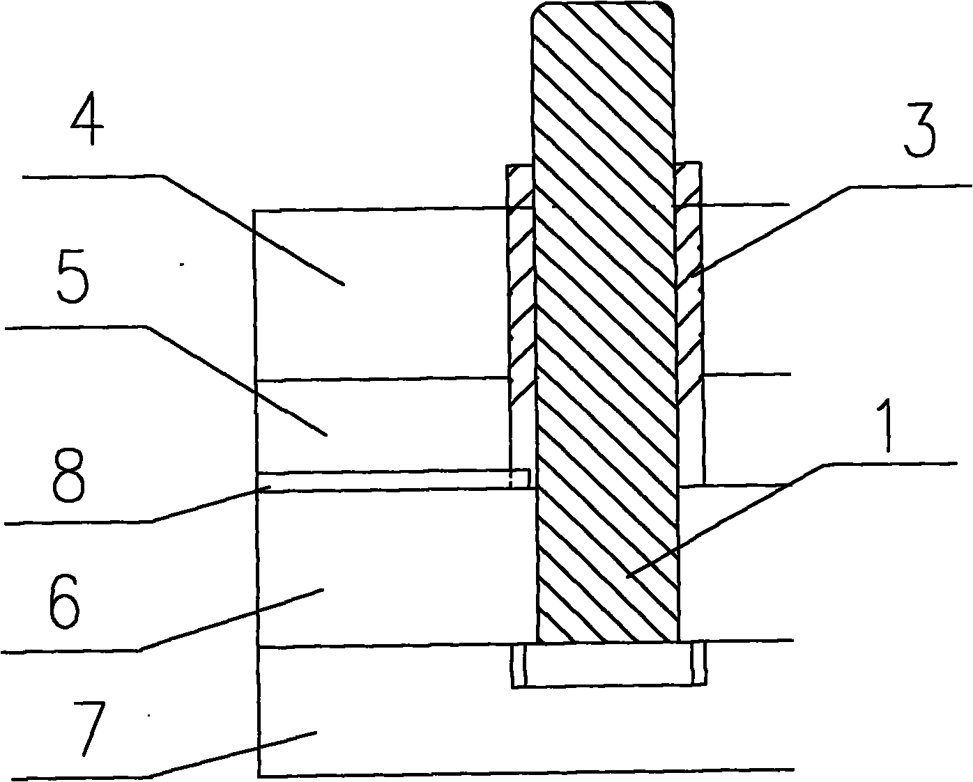
[0013] Such as figure 1 Shown is a schematic structural diagram of a mold without a guide bush installed in the prior art. It can be seen that the guide column 1 is fixed in the lower punch fixing plate 6 and the punch pad 7, and above the guide column 1, there are a stripping back plate 5 and a stripping plate 4, and a stripping back plate 5 and a stripping plate 4 There is an annular hole 2 at a position corresponding to the guide post 1. The annular hole 2 is used to fix the guide sleeve 3 by potting glue. Before the potting preparation, we install the template, and the guide post is also installed in the template, and the template and the guide post are locked tightly. At this time, try to match The gap between the guide post 1 and the guide sleeve 3. At this time, the guide sleeve 3 is relatively loose in the annular hole 2 in the template. Place the guide sleeve 3 in the an


PUM


Abstract

The invention relates to a guide sleeve removing device in a die, which comprises guide pillars (1) fixed in a punch fixing plate (6) and a punch bolster (7), a stripper pad (5) and a stripper plate (4), and guide sleeves (3) fixed in annular holes (2), wherein the upper parts of the guide pillars (1) are provided with the stripper pad (5) and the stripper plate (4) in turn; the positions on the stripper pad (5) and the stripper plate (4) corresponding to the guide pillars (1) are provided with the annular holes (2); and at least one through hole (8) is formed in the stripper pad (5) to communicate the outer space of the die with a space formed by the guide pillars (1), the inner wall of the stripper pad (5), the upper surface of the punch fixing plate (6) and the bottoms of the guide sleeves (3). The guide sleeve removing device has the advantages that the defect that the guide sleeve which falls into a fixed die plate can be taken out only by disassembling the die plate again conventionally is overcome by the guide sleeve removing device in the die; and the guide sleeves are taken out by simply and conveniently blowing air into the through hole by using a high-pressure air source.

Description


Claims


Application Information

Patent Timeline
Owner SUZHOU UIGREEN MICRO & NANO TECH CO LTD
Why Eureka
Try Eureka