Embedded smart card and manufacturing method thereof

An embedded smart card and manufacturing method technology, which is applied in the direction of recording carriers used in machines, instruments, computer components, etc., can solve the problems of not conforming to circular economy, energy saving and emission reduction, not satisfying users, and unable to expand the design, etc., to achieve huge Effect of market space and promotion value, ease of use, rich variety

Inactive Publication Date: 2010-11-10
上海卡美循环技术有限公司
View PDF3 Cites 9 Cited by
  • Summary
  • Abstract
  • Description
  • Claims
  • Application Information

AI Technical Summary

Benefits of technology

This patented technology improves on existing methods that are prone to damage from impacting objects like people's hands during installation. It also allows for flexibility when choosing metals, composites, ceramics, plastics, etc., while still maintaining their functionality over time. Overall, this new embedding system simplifies production processes and enhances security fidelity without compromising any benefits compared to older designs.

Problems solved by technology

The technical problem addressed by this patented method for producing or making contactlessly intelligible electronic devices that have their own power source without being burdensomely designed into one piece while still maintaining environmental benefits.

Method used


Image

  • Embedded smart card and manufacturing method thereof
  • Embedded smart card and manufacturing method thereof
  • Embedded smart card and manufacturing method thereof

Examples


Embodiment Construction

[0044] The following combination Figure 1 to Figure 9 , to describe preferred embodiments of the present invention in detail.

[0045] One of embodiment:

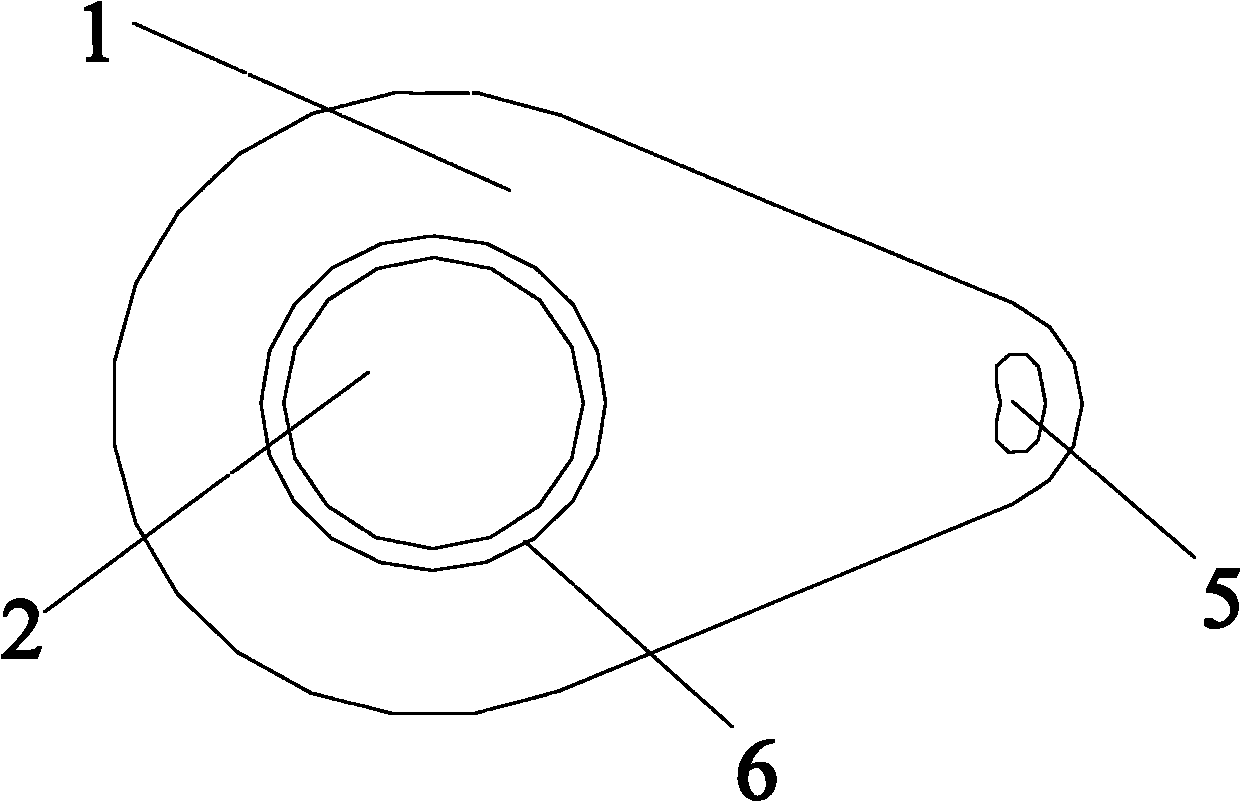
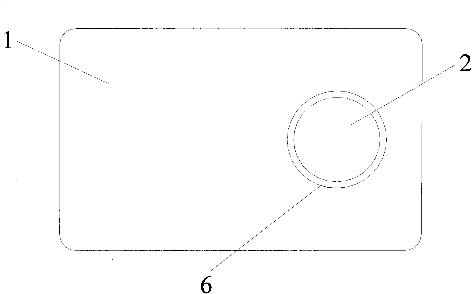
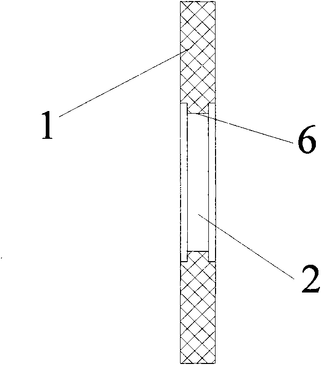
[0046] Such as figure 1 and figure 2 as shown, figure 1 and figure 2 It is a structural schematic diagram of one of the embodiments of the present invention.

[0047] This embodiment discloses an embedded smart card, which includes a card substrate 1 and an antenna circuit module 2 . The antenna circuit module 2 can be arranged at any position of the card base body 1, and any position on the card base body 1 can be provided with an inlay hole 6 for installing the antenna circuit module 2. The shape of the inlay hole 6 is similar to the outer contour of the antenna circuit module 2. For adaptation, the antenna circuit module 2 is fixedly arranged in the inlay hole 6 , and the antenna circuit module 2 is detachably connected to the card base 1 . The antenna circuit module 2 comprises a contactless chip 3 packaged toget


PUM


Abstract

The invention provides an embedded smart card. The embedded smart card comprises a card substrate of any shape and an antenna circuit module, wherein the antenna circuit module is arranged on the card substrate; an embedding hole used for arranging the antenna circuit module is reserved on the card substrate; and the shape of the embedding hole is matched with the outer contour of the antenna circuit module. The antenna circuit module is an insulator, is fixedly arranged in the embedding hole and is detachably connected with the card substrate. The invention also provides a manufacturing method for the embedded smart card, which comprises the following steps of: selecting the ordinary card-shaped card substrate made of a special material according to the occasion at which the card is used and the application of the card; correspondingly reserving a circular embedding hole matched with the card substrate on the card substrate according to the size and the shape of the antenna circuit module; aligning and positioning the antenna circuit module and the embedding hole on the card substrate; curing the antenna circuit module in the embedding hole reserved on the card substrate by a method of high-frequency welding or hot stamping; and performing function expansion and beautification on the card substrate and the antenna circuit module.

Description


Claims


Application Information

Patent Timeline
Owner 上海卡美循环技术有限公司
Why Eureka
Try Eureka