Vent hole pricking device

A vent hole and cylinder technology, applied in the field of casting molding, can solve the problems of ineffective quality assurance, high manufacturing cost, and low production efficiency, and achieve the effects of improving efficiency, ensuring quality, and reducing labor intensity

Inactive Publication Date: 2011-04-13
SUZHOU SUZHU FOUNDRY MACHINERY MFG
View PDF1 Cites 7 Cited by
  • Summary
  • Abstract
  • Description
  • Claims
  • Application Information

AI Technical Summary

Problems solved by technology

[0002] In the process of sand casting, it is necessary to drill vent holes on the sand core to draw out the gas in the sand core, which can avoid the generation of air holes in the casting and improve the quality of the casting. The way of piercing the holes manually with a piercing needle, this method can meet the requirements for a single sand core or sand core group, but in mass production, because there are too many positions and numbers of holes that need to be pierced, it is ne

Method used


Image

  • Vent hole pricking device
  • Vent hole pricking device

Examples


Embodiment Construction

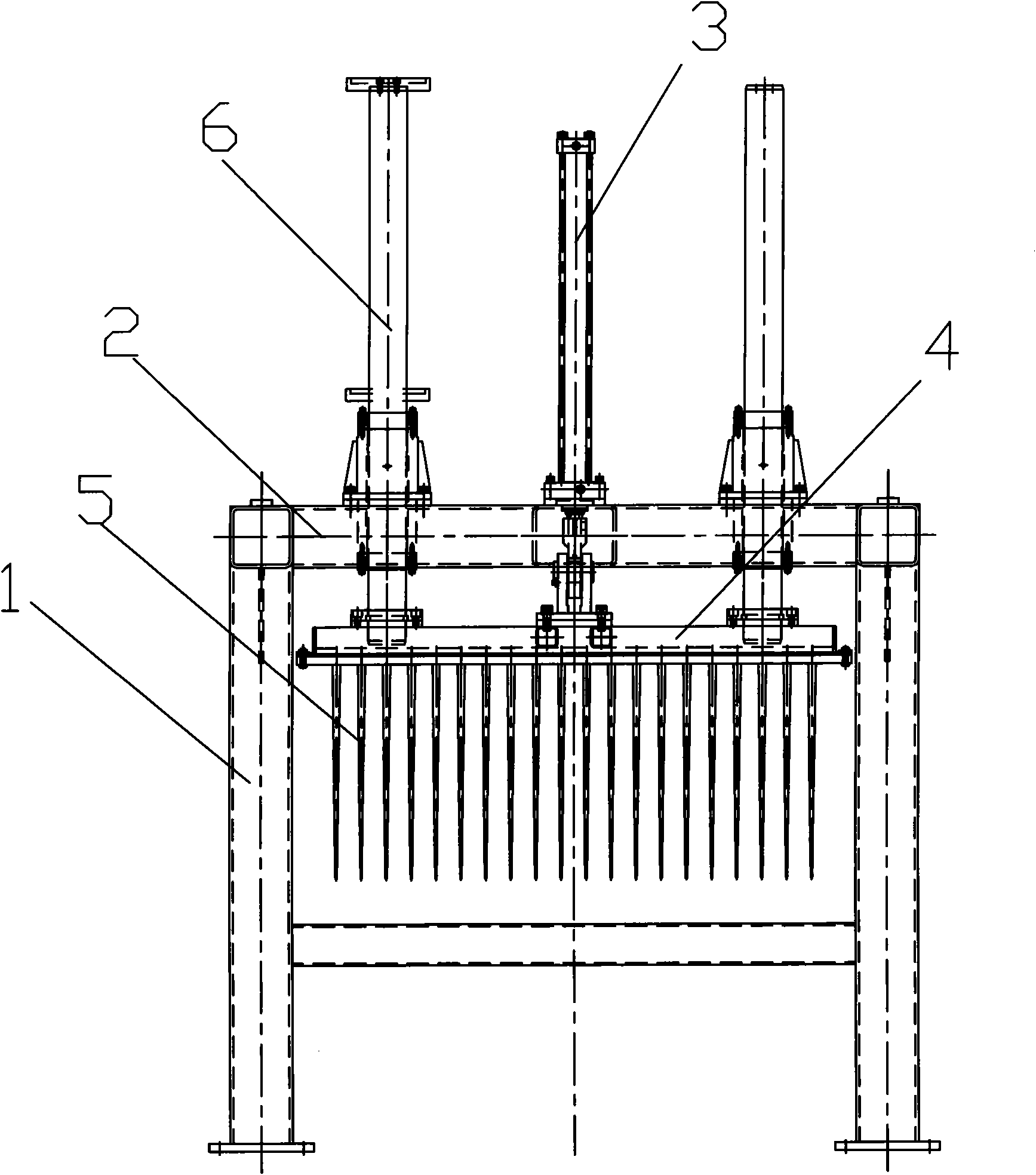
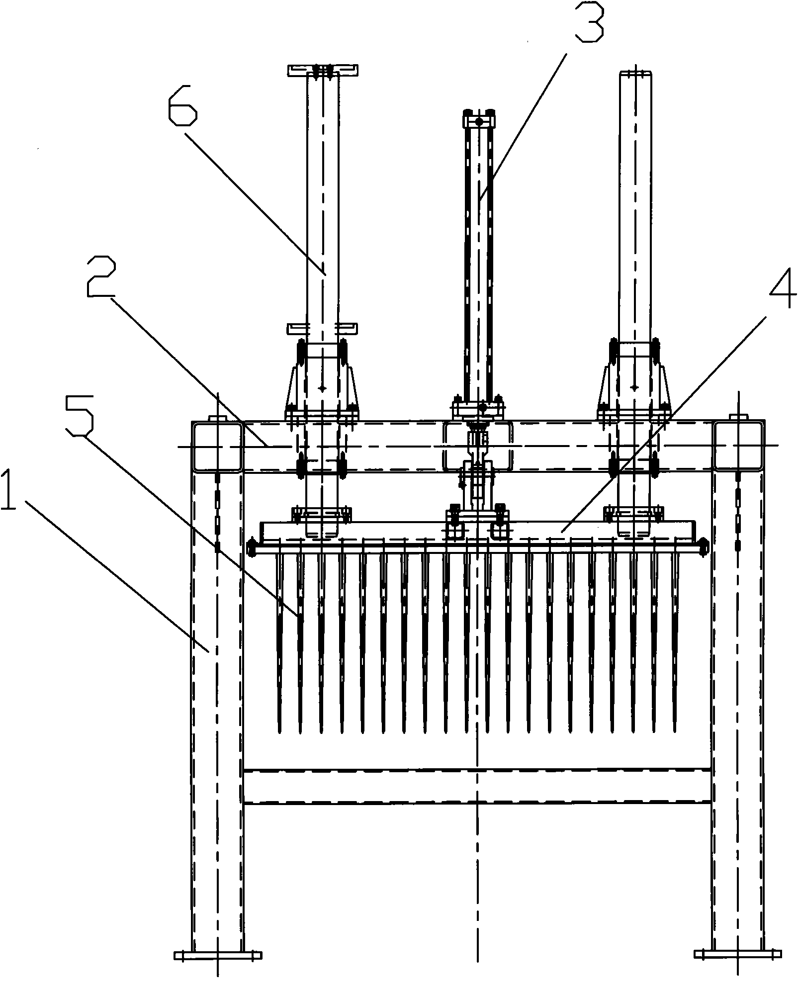
[0011] Preferred embodiments of the present invention will be described in detail below in conjunction with the accompanying drawings.

[0012] Such as figure 1 As shown, the air vent device includes a mounting bracket 1, a beam 2 is arranged on the top of the mounting bracket 1, a cylinder 3 is arranged on the beam 2, the piston rod of the cylinder 3 is connected with a needle mounting plate 4, and the needle mounting plate 4 is There are several needles 5. A guide column 6 is respectively arranged on both sides of the cylinder 3 , and the guide column 6 can slide through the beam 2 and connect with the needle mounting plate 4 . When the piston rod of the cylinder 3 drives the needle mounting plate to move up and down, the guide post 6 can play a guiding role.

[0013] When the air vent device is in use, the sand core is first placed under the needle mounting plate, and then the cylinder is driven to move the needle mounting plate downward, so that the needle pierces several v


PUM


Abstract

The invention discloses a vent hole pricking device, which comprises a mounting bracket, wherein the top of the mounting bracket is provided with a beam, the beam is provided with a cylinder, the piston rod of the cylinder is connected with a needle mounting plate, and the needle mounting plate is provided with multiple needles. When in use, a core is arranged below the needle mounting plate, and then the cylinder is driven, so that the needle mounting plate moves downwards so as to prickle multiple vent holes on the core by the needle. The device has simple structure, is convenient in use, and can prickle the multiple vent holes on the core once, thereby improving the vent hole prickling efficiency, lowering the labor intensity of workers, and effectively ensuring the quality of castings.

Description


Claims


Application Information

Patent Timeline
Owner SUZHOU SUZHU FOUNDRY MACHINERY MFG
Why Eureka
Try Eureka