Photoetching machine worktable with driving device capable of balancing torque

A technology of driving device and balancing torque, applied in microlithography exposure equipment, photolithographic process exposure devices, etc., can solve the problems of interference, affecting control accuracy, and difficulty in the same height.

Active Publication Date: 2011-04-13
SHANGHAI MICRO ELECTRONICS EQUIP (GRP) CO LTD +1
View PDF1 Cites 11 Cited by
  • Summary
  • Abstract
  • Description
  • Claims
  • Application Information

AI Technical Summary

Benefits of technology

In this new design described in this patented technology, there are two main technical features: one involves adding extra motors or other components called Y direction (X) compensators to correct any misalignments during operation; another focuses on improving the performance of the system's rotating parts like bearings due to their asymmetry.

Problems solved by technology

LCD manufacturing involves aligning multiple wafers with each other before they go into production lines. To improve productivity while maintaining accurate alignment requires faster and more stable movements along both directions within the tool's frame. Current methods require larger motors or higher speeds which increase weight but decrease efficiency. Additionally, current methods have limitations in achieving linearity over longer distances without adding extra components like servo systems.

Method used


Image

  • Photoetching machine worktable with driving device capable of balancing torque
  • Photoetching machine worktable with driving device capable of balancing torque
  • Photoetching machine worktable with driving device capable of balancing torque

Examples


Embodiment Construction

[0020] In order to better understand the technical content of the present invention, specific embodiments are given together with the attached drawings for description as follows.

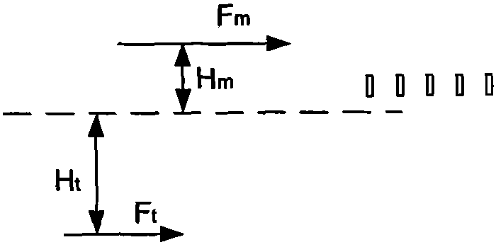
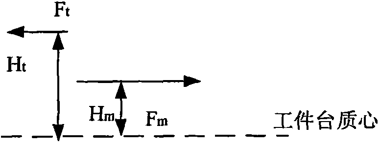
[0021] Please refer to Figure 2a ~ Figure 2c , Figure 2a ~ Figure 2c Shown is the schematic diagram of the moment compensation of the center of mass of the workpiece table of the lithography machine at different positions.

[0022] If the center of mass of the workpiece table is in the middle of the two motors, the mass of the workpiece table is M, and the acceleration is A, then the driving force F of motor 1-1 is compensated m and the force F driving the motor 1-2 t Then there is the following relationship:

[0023]

[0024]

[0025] where H m and H t represent the distances from the compensation motor and drive motor to the center of mass of the workpiece table respectively. In actual work, as long as the force F of the compensation motor 1-1 is controlled t The size of the additional


PUM


Abstract

The invention provides a photoetching machine worktable with a driving device capable of balancing torque, comprising a coarse motion part and an inching part. The coarse motion part comprises an X-direction part and a Y-direction part which is arranged at the bottom of the X-direction part, the X-direction coarse motion part is provided with an X-direction driving motor and an X-direction comprehension motor, and the Y-direction coarse motion part is provided with a Y-direction driving motor. The photoetching machine worktable with the driving device capable of balancing the torque, which is proposed by the invention, adopts a motor as a main driving motor of the worktable and another motor to be in parallel with the former motor so as to eliminate additional torque, i.e. the two motors are combined to eliminate the additional torque which is generated by the driving force and the centroid mismatching of the motors.

Description


Claims


Application Information

Patent Timeline
Owner SHANGHAI MICRO ELECTRONICS EQUIP (GRP) CO LTD
Why Eureka
Try Eureka