Cloth cutting device of hole stitching machine

A technology for sewing machines and buttonholes, which is applied in the direction of sewing machine control devices, sewing machine components, and program-controlled sewing machines. Effects of misalignment, relaxation of contact pressure, and prevention of mutual damage

Active Publication Date: 2011-04-20
JUKI CORP
View PDF2 Cites 8 Cited by
  • Summary
  • Abstract
  • Description
  • Claims
  • Application Information

AI Technical Summary

Problems solved by technology

This will cause excessive impact on the cutter, causing damage to th

Method used


Image

  • Cloth cutting device of hole stitching machine
  • Cloth cutting device of hole stitching machine
  • Cloth cutting device of hole stitching machine

Examples


Embodiment Construction

[0037] (Overall structure of buttonhole overlock sewing machine with round head)

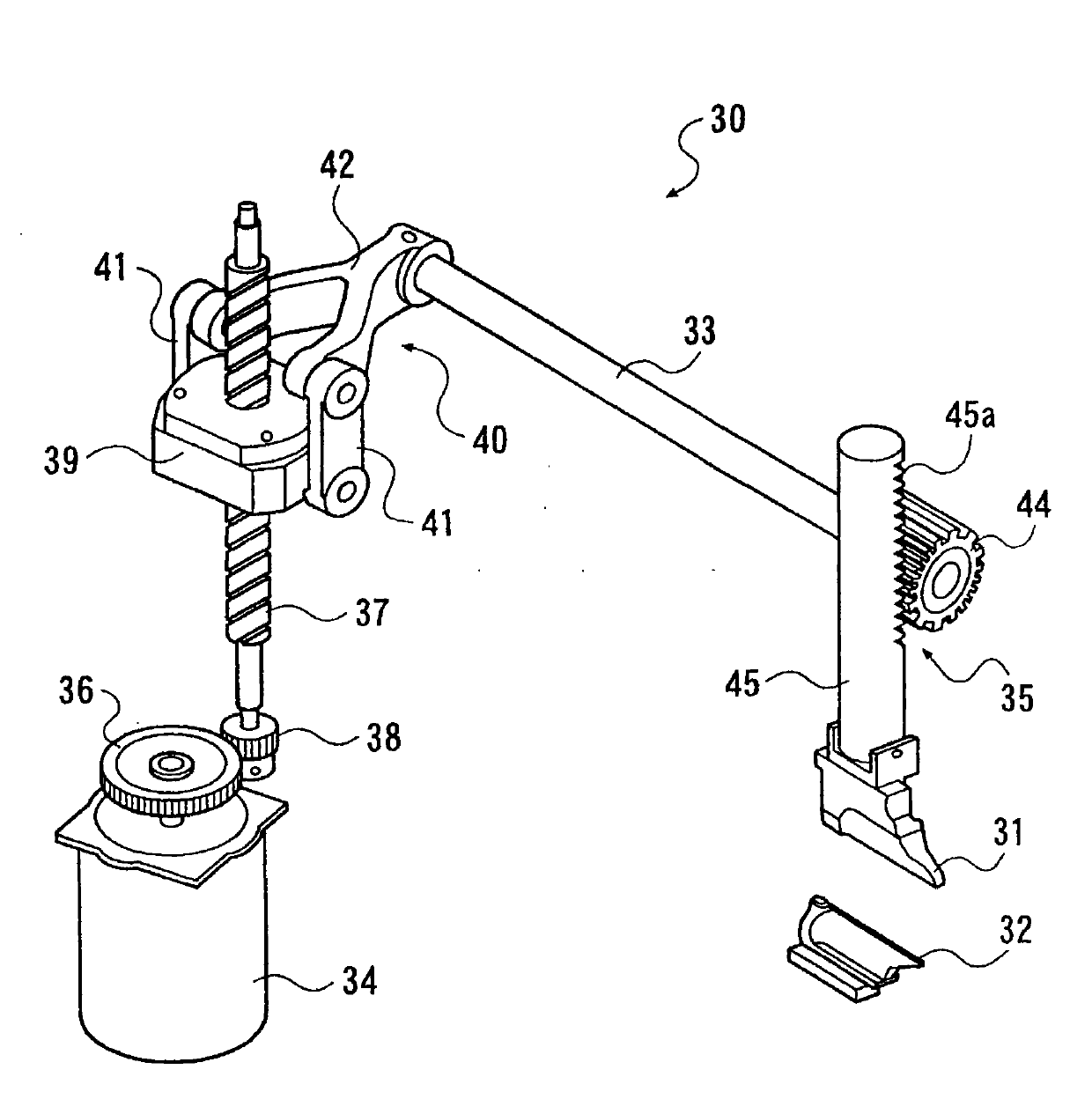
[0038] The cloth cutting device 30 in the embodiment of the present invention will be described with reference to the drawings.

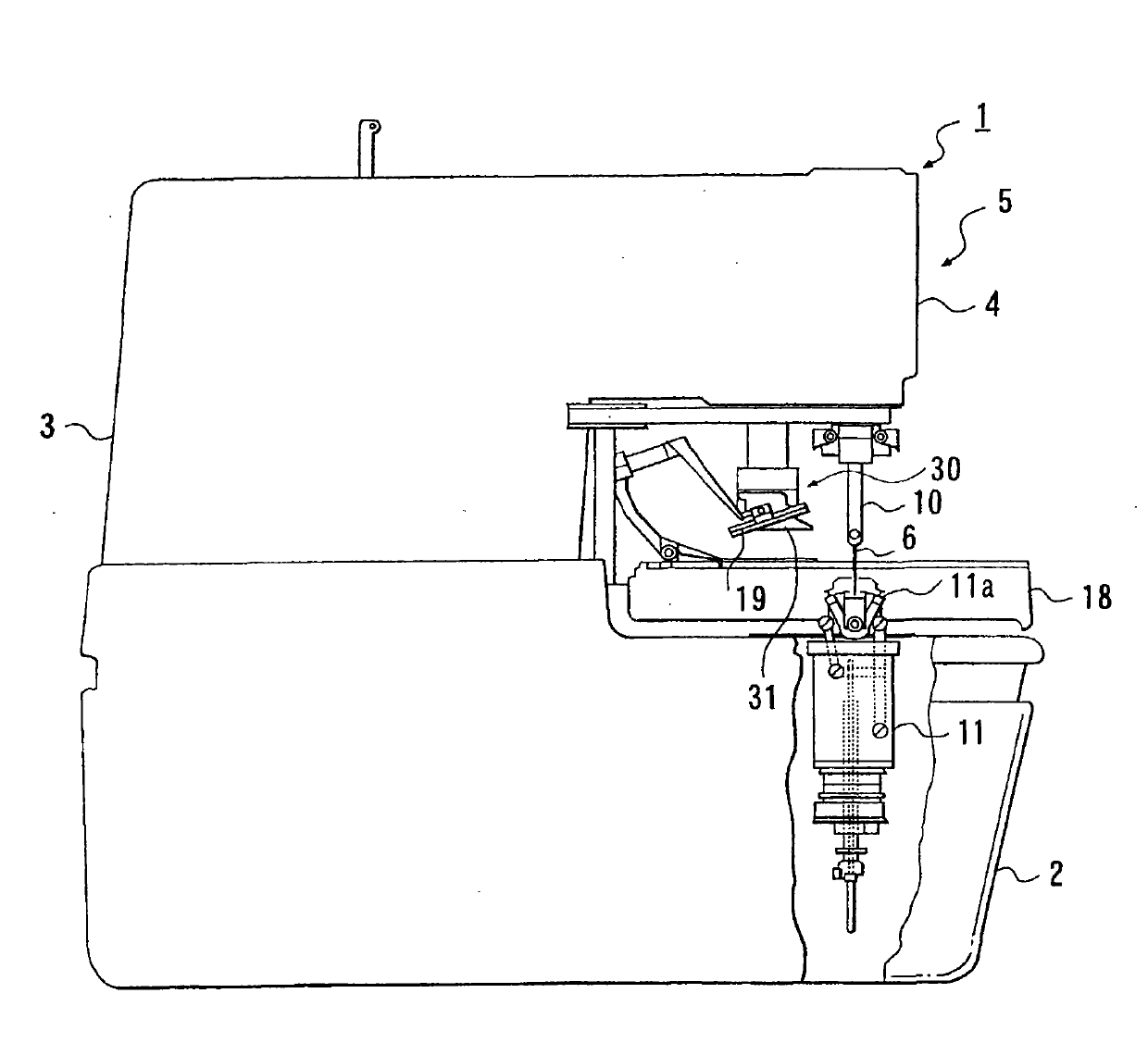
[0039] Such as figure 1 As shown, there is a cloth cutting device 30 (in figure 2 The ball head buttonhole overlock sewing machine 1 shown in the figure) has a basic structure as a sewing machine for ball head buttonhole overlock sewing. The buttonhole sewing machine 1 has a sewing machine frame 5 and a sewing machine table on which the sewing machine frame 5 is placed. The sewing machine frame 5 has: a base part 2 formed in a substantially rectangular box shape; a longitudinal body part 3 provided on the base the rear part of the body part 2;

[0040] In addition, a needle bar 10 is provided at the front end of the arm 4, which extends downward, and has a sewing needle 6 at the lower end, which can move up and down and swing left and right. And, in the base part 2,


PUM


Abstract

The invention relates to a cloth cutting device of hole stitching machines, wherein period time is not lost and right pressing force is easily to be set.The cloth cutting device (30) comprises a knife (32), a knife receiver (31), a moving mechanism (35) which moves the knife (32) or the knife receiver (31), a pulse motor (34) which serves as a drive source of the movement of the knife or the knife receiver, a rotation amount detector (55) which detects a rotation amount of the pulse motor, and a controller (50) which controls the pulse motor.; The controller executes a control to switch the movement of the knife or the knife receiver to be low speed on its way, and includes a cutting control means (50c) which controls the pulse motor to stop driving if a deviation determining means determines that the deviation of the pulse motor reaches the set value, and a current control means (50c) which limits, during the low-speed movement, a current value applied to the pulse motor to be lower than that during a high-speed movement.

Description


Claims


Application Information

Patent Timeline
Owner JUKI CORP
Why Eureka
Try Eureka