High-pressure paint film continuity tester

A continuity and tester technology, applied in instruments, scientific instruments, measuring devices, etc., can solve the problems of large waste, poor continuity of the paint film of the finished product line, and inability to reflect the truth, and achieve simple structure, reduced testing cost, and location Easy to set effects

Active Publication Date: 2011-04-27
TONGLING JINGDA REA SPECIAL ENAMELED WIRE
View PDF0 Cites 8 Cited by
  • Summary
  • Abstract
  • Description
  • Claims
  • Application Information

AI Technical Summary

Problems solved by technology

This method mainly has the following disadvantages: 1. It is necessary to wait for the finished product line to be taken off the line before it can be taken out for inspection, which affects the normal production and causes a lot of waste. It can reflect the continuity of the paint film of the 30m finished line, but for the finished line with a shaft of tens of thousands of meters or even hundreds of thousands of meters, this method has certain limitations

Method used


Image

  • High-pressure paint film continuity tester
  • High-pressure paint film continuity tester
  • High-pressure paint film continuity tester

Examples


Example Embodiment

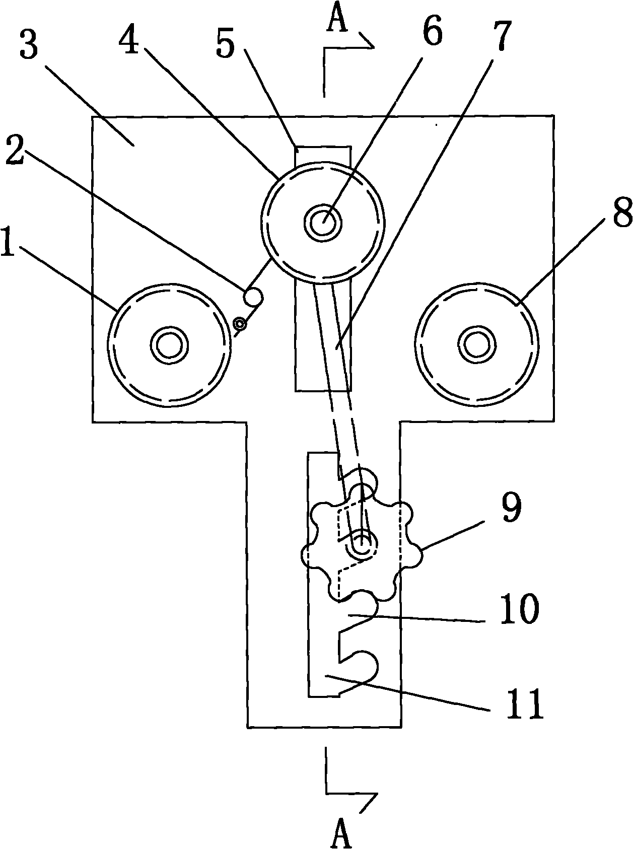
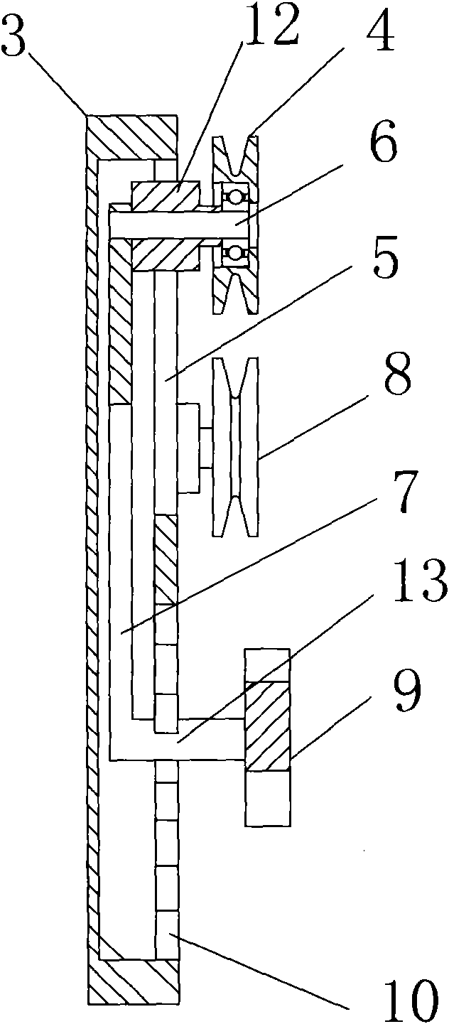
[0011] like figure 1 , figure 2 As shown, the high-voltage test head consists of a bracket 3, left and right guide wheels 1, 8 fixed on the bracket 3, and a pressure line wheel 4 located in the middle of the left and right guide wheels. The pressure line wheel 4 is fixed on the vertical displacement adjustment device. On the bracket 3, the vertical displacement adjustment device is a tie rod 7, and the bracket 3 is provided with a vertical guide groove 5 for the up and down movement of the pressure roller shaft 6, the slider 12 installed in the vertical guide groove 5, and the pressure roller shaft 6 and the slide. The block 12 is connected with a rotating width, the pull rod 7 is arranged under the pressure wire wheel 4, the upper end of the pull rod 7 is hinged on the pressure wire wheel shaft 6, the lower end of the pull rod 7 is connected with a positioning pin 13 perpendicular to the pull rod 7, and the bracket 3 is provided with a pull rod. The vertical guide groove 11 th


PUM


Abstract

The invention relates to a high-pressure paint film continuity tester, which comprises a high pressure test head, a direct-current high pressure generator, a signal detection circuit, a processing circuit and a counting instrument, wherein the high pressure test head consists of a bracket, left and right guide wheels fixed on the bracket, and a creaser wheel positioned in the middle of the left and right guide wheels; and the creaser wheel or the left and right guide wheels is/are fixed on the bracket through a vertical displacement adjusting device. The vertical position between the creaser wheel and the guide wheels on the high pressure test head is adjustable, so continuity online detection of enameled wires and paint films can be realized, detection materials are not dissipated, and the test cost is reduced; and the tester has a simple structure, and the positions of the creaser wheel and the guide wheels are convenient to set.

Description


Claims


Application Information

Patent Timeline
Owner TONGLING JINGDA REA SPECIAL ENAMELED WIRE
Why Eureka
Try Eureka