Turning and rolling compound machine tool simulation cutting loading device and using method

A compound machine tool and loading device technology, which is applied in the direction of measuring devices, machine/structural component testing, instruments, etc., can solve problems such as low applicability, inability to simulate machine tool processing conditions, and inability to fully simulate machine tool loading force, etc., to achieve applicable Highly Reliable, Inexpensively Tested, Powerful Effects

Pending Publication Date: 2021-04-09
SOUTH CHINA UNIV OF TECH +1
View PDF1 Cites 0 Cited by
  • Summary
  • Abstract
  • Description
  • Claims
  • Application Information

AI Technical Summary

Problems solved by technology

This patent can simulate the actual machining conditions of the machine tool on the test platform for sports car experiments, but this patent can only generate the loading force in one radial direction of the spindle, and cannot fully simulate the complex loading force received by the machine tool during actual machining. Applicability is not high
[0007] The patent name is a loading experimental device for simulating cutting force of a tool (application number: 201720764482.7) which discloses a loading experimental d

Method used


Image

  • Turning and rolling compound machine tool simulation cutting loading device and using method
  • Turning and rolling compound machine tool simulation cutting loading device and using method
  • Turning and rolling compound machine tool simulation cutting loading device and using method

Examples


Example Embodiment

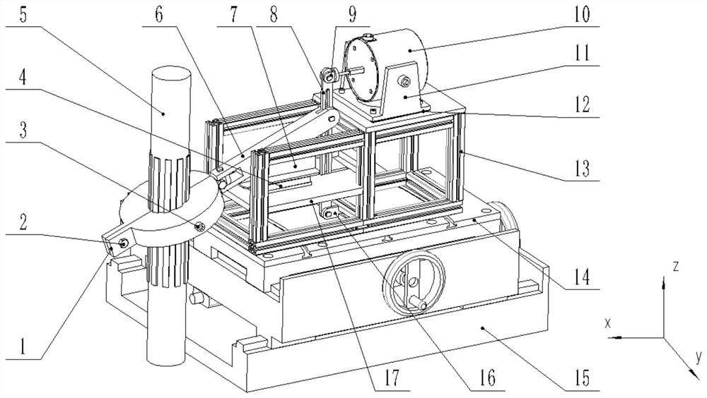
[0045]In order to facilitate understanding of the invention, the present invention will be further described below with reference to the accompanying drawings and specific embodiments. The preferred embodiment of the present invention is given in the drawings. However, the present invention can be implemented in many different forms, is not limited to the embodiments described herein. Conversely, the purpose of providing these embodiments is to make the disclosure of the present invention more thoroughly.

[0046]It should be noted that when the element is referred to as "fixed to" another element, it can be directly in another element or may also exist. When a component is considered to be "connected" another element, it may be directly connected to another element or may always exist in the center element. The term "vertical", "horizontal", "left", "right", "left", "right", and similar expressions are not shown as unique embodiments.

[0047]All techniques and scientific terms used herein


PUM


Abstract

The invention discloses a turning and rolling composite machine tool simulation cutting loading device and a using method. The device comprises a cross sliding table, a base, a rigid support, a workpiece motion simulation assembly, a loading force amplification assembly, a cutting force simulation loading assembly and a test rod, the base is installed on the cross sliding table, the rigid support is installed on the base, the workpiece motion simulation assembly is installed in the middle of the rigid support, the cutting force simulation loading assembly is installed at the upper end of the rigid support, the loading force amplification assembly is installed inside the rigid support, and the upper end of the loading force amplification assembly is connected with the cutting force simulation loading assembly. The using method comprises the steps that the simulated cutting loading device is fixed to a machine tool workbench, and a test rod is installed at a machine tool tooling station and clamped; the cutting force simulation loading assembly is used for generating excitation force applied by testing, the load characteristics of the machine tool in the machining state are simulated, and then the dynamic characteristic performance of the machine tool under the excitation load is tested.

Description


Claims


Application Information

Patent Timeline
Owner SOUTH CHINA UNIV OF TECH
Why Eureka
Try Eureka