Extrusion type rubber bushing structure

A rubber bushing and bushing technology, applied to springs, springs/shock absorbers, mechanical equipment, etc. made of plastic materials, can solve the problems of non-replaceable and difficult rubber bushings, and achieve simple structure and cost saving , the effect of easy replacement

Inactive Publication Date: 2011-06-29
CHERY AUTOMOBILE CO LTD
View PDF10 Cites 6 Cited by
  • Summary
  • Abstract
  • Description
  • Claims
  • Application Information

AI Technical Summary

Problems solved by technology

[0003] The purpose of the present invention is to provide an extrudable rubber bushing structure to s

Method used


Image

  • Extrusion type rubber bushing structure
  • Extrusion type rubber bushing structure
  • Extrusion type rubber bushing structure

Examples


Embodiment 1

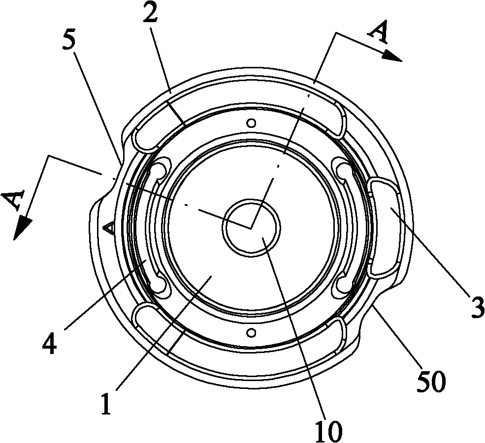
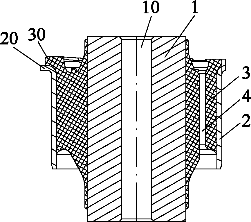
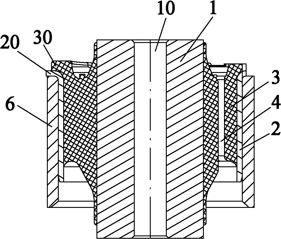
[0017] Example 1, such as Figure 1 to Figure 3 As shown, an extrudable rubber bushing structure, the rubber bushing is pressed into the bushing sleeve 6 fixed on the vehicle body bracket or torsion beam, which includes a bushing inner tube 1 and a bushing outer tube 2 And the rubber layer 3 vulcanized between the bush inner tube and the bush outer tube, the materials of the bush inner tube 1 and the bush outer tube 2 are all cast iron; the bush inner tube 1 is provided with a bush inner hole 10. Fixing bolts are passed through the inner hole 10 of the bushing to fix it on the vehicle body; the outer tube 1 of the bushing is provided with an outer tube flanging 20, and the rubber layer is vulcanized until the outer tube flanging forms a rubber layer Flanging 30, the diameter of outer tube flanging 20 is larger than the diameter of the bushing sleeve 6 used for press-fitting the rubber bushing; the outer tube flanging 20 and the rubber layer flanging 30 are provided with a group o


PUM


Abstract

The invention discloses an extrusion type rubber bushing structure. The rubber bushing structure comprises a bushing inner pipe, a bushing outer pipe and a rubber layer, wherein the rubber layer is vulcanized between the bushing inner pipe and the bushing outer pipe; a bushing inner hole is formed on the bushing inner pipe; the bushing outer pipe is provided with an outer pipe turned-over edge; the rubber layer is vulcanized till a rubber layer turned-over edge is formed on the outer pipe turned-over edge; two groups of notches are respectively formed on the outer pipe turned-over edge and the rubber layer turned-over edge in the same positions; and a slotted hole is formed on the rubber layer. When a rubber bushing is extruded, supporting points (namely, the notches) for exerting force in an opposite direction are arranged on the sleeve of the bushing, so that the bushing can be extruded conveniently. The rubber bushing has the advantages that the structure is simple; the replacement is convenient; no component is added; and the cost is saved.

Description


Claims


Application Information

Patent Timeline
Owner CHERY AUTOMOBILE CO LTD
Why Eureka
Try Eureka