Laminated laminated stator and manufacturing method thereof

A technology of interlocking and stator, which is applied in the manufacture of laminated interlocking stator and the field of laminated interlocking stator, can solve the problems of difficulty in reducing product cost, small winding operation space, and high cost of winding process, and achieves high assembly work efficiency. , The effect of reducing the winding process requirements and easy implementation of assembly operations

Active Publication Date: 2011-12-14
浙江迪贝电气股份有限公司
View PDF6 Cites 2 Cited by
  • Summary
  • Abstract
  • Description
  • Claims
  • Application Information

AI Technical Summary

Benefits of technology

This new type of electric rotating machines (motors) has several benefits compared to older designs that were previously used for their purpose. These improvements include improved performance without requiring excessive maintenance or downtime during installation, lower costs associated with manufacturing processes, higher speeds at which they rotate faster than previous models, better control over electromagnetic fields, enhanced coolability, etc., resulting in longer lifespan and more efficient energy usage.

Problems solved by technology

This patented problem addressed in this patents relates to improving the production rate for motors while reducing costs associated therewith without sacrificing their overall quality or functionality. Specifically, current methods require laborious steps such as manually inserting cores into bobbins during welding processes, resulting in decreased throughput compared to automated machines used widely throughout industry today. Additionally, existing solutions have limited effectiveness because they are often slower and less efficient, leading to increased operating expenses overtime.

Method used


Image

  • Laminated laminated stator and manufacturing method thereof
  • Laminated laminated stator and manufacturing method thereof
  • Laminated laminated stator and manufacturing method thereof

Examples


Embodiment Construction

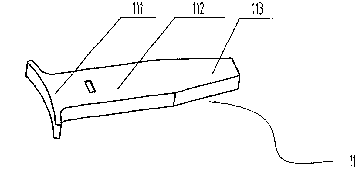
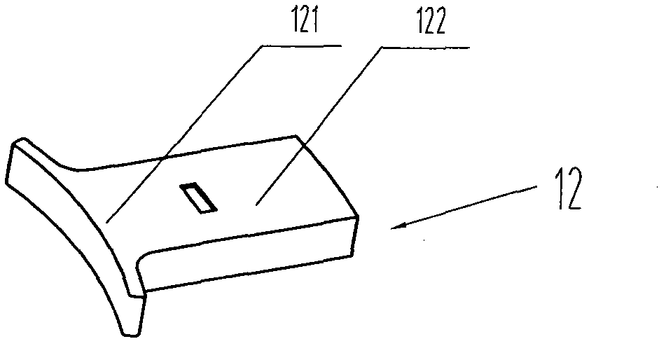
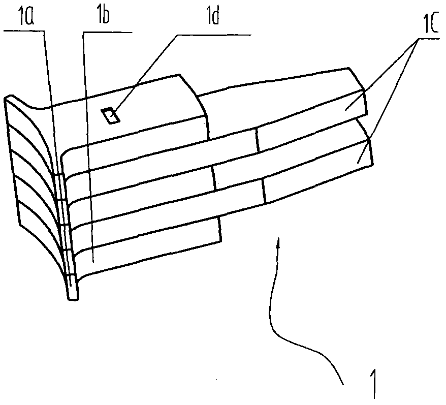
[0038] see figure 1 and figure 2 As shown, the long pole shoe punching piece 11 is T-shaped, and it is a single whole made up of the boot crown 111, the boot body 112 and the boot foot 113. The far end of the boot foot 113 is pointed, while the short pole shoe punching piece 12 is a single whole consisting of a boot crown 121 and a boot body 122, wherein the long pole shoe punch 11 and the short pole shoe punch 12 have the same thickness, and the shape and size of the boot crown 111 and the boot crown 121 are Similarly, the boot body 112 and the boot body 122 have the same width. exist image 3 Among them, the pole shoe module 1 is composed of a shoe crown part 1a, a shoe body part 1b and a shoe foot part 1c. As an example, the pole shoe module 1 is stacked alternately with three short pole shoe punches 12 and two long pole shoe punches 11, riveted and fixed together, and then fixed to each other by the rivet 1d provided on the shoe body 1b. It can be seen that the shoe body


PUM


Abstract

The invention discloses a lamination tabling type stator which is formed by tabling a plurality of pole shoe modules of independently wound coils with a magnetic conductor provided with a center hole in a radial mode, wherein each pole shoe module is formed by alternately laminating and riveting long and short pole shoe punched sheets; the magnetic conductor is formed by alternately laminating a plurality of magnetic conducting ring cut sheets, which are arranged circumferentially and annularly at intervals, together with magnetic conducting ring punched sheets; inlaying gaps which have complementary shapes and are in same number with shoe feet of all the pole shoe modules are formed between adjacent magnetic conducting ring cut sheets of each layer of the magnetic conductor; and the poleshoe modules and the magnetic conductor are fixedly connected into a whole after being inlaid together. The invention also provides a manufacturing method of the lamination tabling type stator, and the method is low in winding process requirement, high in winding speed and easy in assembly. According to the manufacturing method of the stator structure and formation, the pole shoe modules are convenient in winding operation outside the stator, the winding process requirement is reduced, multi-head neck-and-neck winding of the pole shoe modules is realized, the winding productivity in unit timeis high, the winding cost is low, the winding slot fullness is high, the motor efficiency is improved, the pole shoe modules are inserted in the magnetic conductor after being subjected to winding, the assembly is easy to implement, and the working efficiency is high.

Description


Claims


Application Information

Patent Timeline
Owner 浙江迪贝电气股份有限公司
Why Eureka
Try Eureka