Automatic wire press mold workpiece transfer and positioning device

A technology of positioning device and automatic line, applied in positioning device, feeding device, storage device, etc., can solve the problems of inability to place, influence, and release the conveying mechanism.

Inactive Publication Date: 2011-12-21
SHANDONG WEIFANG FOTON MOLD
View PDF5 Cites 8 Cited by
  • Summary
  • Abstract
  • Description
  • Claims
  • Application Information

AI Technical Summary

Problems solved by technology

The most common feeding method for automatic press-fitting molds is the use of conveyor belt feeding devices. At present, most automated line press-fitting molds use horizontal feeding of the workpiece, but due to the limitations of the mold structure or the shape of the workpiece, the horizontal feeding method cannot be used, or The horizontal feeding method is relatively difficult, and the positioning of the wor

Method used


Image

  • Automatic wire press mold workpiece transfer and positioning device
  • Automatic wire press mold workpiece transfer and positioning device
  • Automatic wire press mold workpiece transfer and positioning device

Examples


Embodiment Construction

[0021] Below in conjunction with accompanying drawing and embodiment, further elaborate the present invention. In the following detailed description, certain exemplary embodiments of the invention are described by way of illustration only. Needless to say, those skilled in the art would realize that the described embodiments can be modified in various different ways, all without departing from the spirit and scope of the present invention. Accordingly, the drawings and description are illustrative in nature and not intended to limit the scope of the claims.

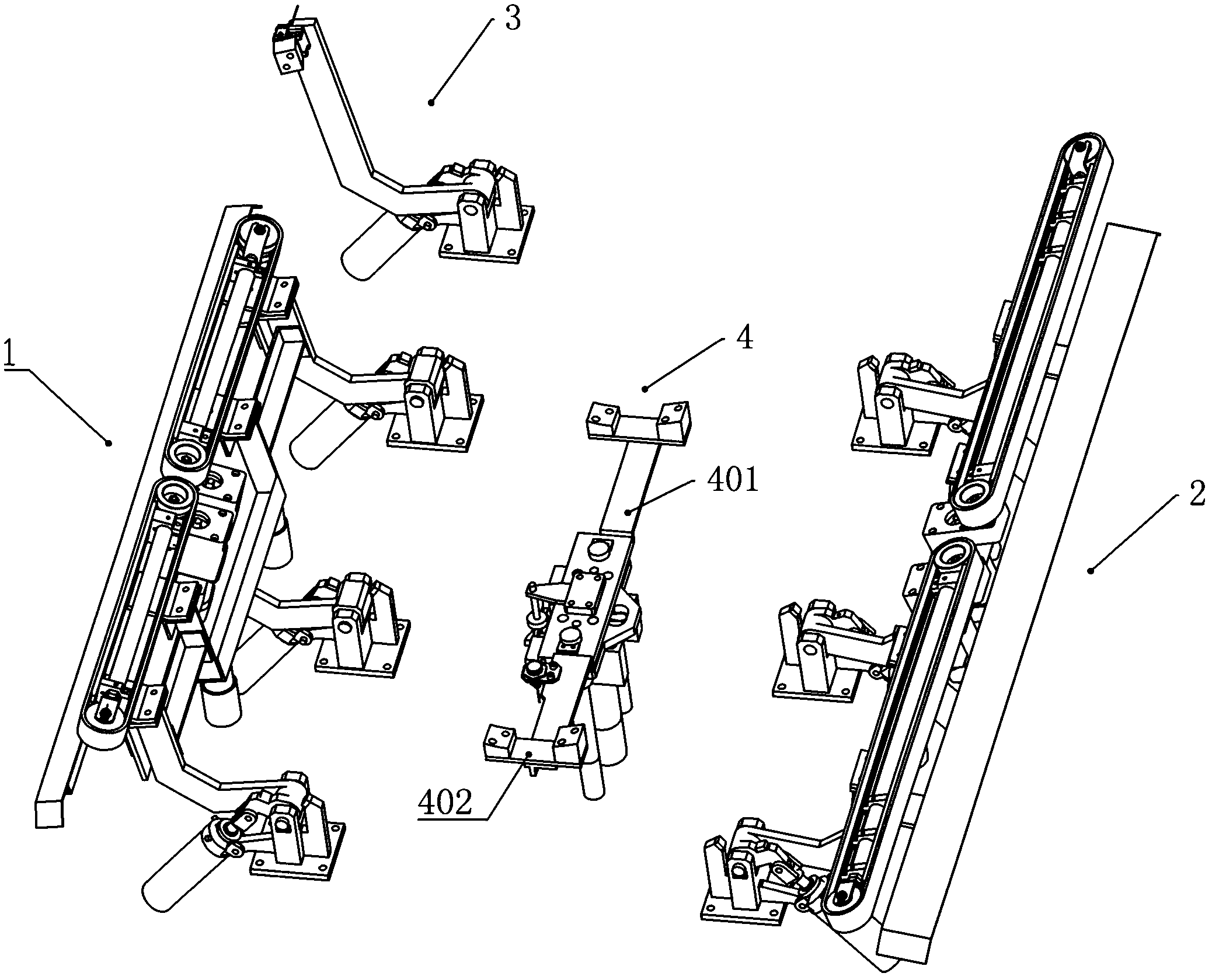
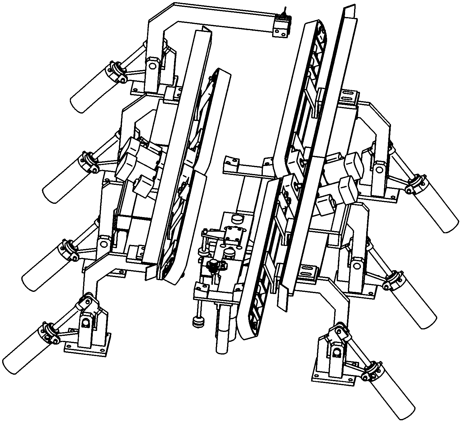
[0022] Such as figure 1 As shown, the automatic line press mold workpiece transmission and positioning device includes a side rotation positioning feeding device, and the side rotation positioning feeding device includes a left rotation positioning feeding device 1 installed oppositely on both sides of the mold surface of the lower mold base of the press and the right rotary positioning feeding device 2, such as image 3


PUM


Abstract

The invention discloses an automatic transferring and positioning device of a line pressing die-assembly workpiece. The automatic transferring and positioning device comprises a side rotary positioning and feeding device, wherein the side rotary positioning and feeding device comprises a left-side rotary positioning and feeding device and a right-side rotary positioning and feeding device; a lower mold seat is also provided with a workpiece lifting device and a rear-side rotary feeding and positioning device; when the device provided by the invention is in working, the side rotary positioningand feeding device rises to a high position, a workpiece is conveyed to the side rotary positioning and feeding device by a charging frame; the device is started to transfer the workpiece to be abovea mold profile of a lower die seat, the rear-side rotary feeding and positioning device is utilized to position the workpice, and then the workpiece lifting device rises and separate the workpiece away from the side rotary positioning and feeding device; the side rotary positioning and feeding device rotates to the original position, the workpiece lifting device falls back, and the workpiece is placed on the mold profile; and the whole feeding and positioning process is finished automatically without artificial interference, the feeding of the narrow and long workpiece with warping parts at the two ends can be realized without influence caused by the mold structure and the workpiece shape.

Description


Claims


Application Information

Patent Timeline
Owner SHANDONG WEIFANG FOTON MOLD
Why Eureka
Try Eureka