Method and device for temperature management of exhaust purification equipment

A technology of exhaust gas purification and equipment, which is applied in the direction of electric control of exhaust treatment devices, exhaust devices, exhaust treatment, etc., can solve the problems of unrelated use, insufficient inclusion of thermoelectric generators, etc., and achieve the effect of improving thermal protection

Inactive Publication Date: 2012-05-09
ROBERT BOSCH GMBH
View PDF7 Cites 14 Cited by
  • Summary
  • Abstract
  • Description
  • Claims
  • Application Information

AI Technical Summary

Problems solved by technology

However, the prior art does not deal with the use of thermoelectric generators at all or

Method used


Image

  • Method and device for temperature management of exhaust purification equipment
  • Method and device for temperature management of exhaust purification equipment
  • Method and device for temperature management of exhaust purification equipment

Examples


Embodiment Construction

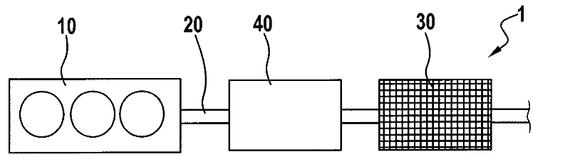
[0040] figure 1 An internal combustion engine 1 is schematically shown with a cylinder bank 10 and an exhaust gas purification system 40 arranged in an exhaust gas duct 20 . The thermoelectric generator 30 is mounted on the exhaust gas purification device 40 upstream of the exhaust gas purification device 40 in the flow direction of the exhaust gas in such a way that it is heated from one side of the hot exhaust gas, while the other side is directed outwards and has a lower temperature. As described above, electrical energy can thus be detected from the thermal energy contained in the exhaust gas. This arrangement is particularly suitable to protect the exhaust gas aftertreatment device 40 from too high temperatures and thus possible thermal damage if the thermoelectric generator 30 is operated in generator mode and thus can extract thermal energy from the exhaust gas.

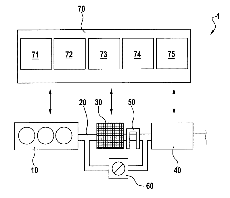
[0041] exist figure 2 Also schematically shows an arrangement in which the thermoelectric generator 30 is c


PUM


Abstract

The present invention provides a method and a device for temperature management of an exhaust purification equipment. The invention relates to a method for temperature management in an exhaust channel of an internal combustion engine, wherein at least one thermoelectric generator is equipped in the exhaust channel or the exhaust purification equipment. The operation mode of the thermoelectric generator comprises: in temperature management of the exhaust purification equipment, when exhaust flow in the exhaust channel or for controlling the exhaust purification equipment, an achievable heating or cooling capacity of the thermoelectric generator and cooling capacity of additional components for cooling the thermoelectric generator are considered. The invention also relates to a device for temperature management of exhaust purification equipment in an exhaust channel of the internal combustion engine. Through totally including cooling or heating capability of the thermoelectric generator in the operation mode of the exhaust purification equipment, the efficiency of the exhaust purification equipment is improved, temperature management is improved and fuel consumption is reduced. The method and the device can be particularly used in an Otto engine or a diesel engine advantageously.

Description


Claims


Application Information

Patent Timeline
Owner ROBERT BOSCH GMBH
Why Eureka
Try Eureka