Overspeed inductor for mine car
A sensor and mine car technology, applied in the direction of equipment with unique mechanical means, can solve the problems of insufficient sensitivity and easy damage of mechanical overspeed sensors, and achieve the effect of simple structure, convenient maintenance and high sensitivity
- Summary
- Abstract
- Description
- Claims
- Application Information
AI Technical Summary
Problems solved by technology
Method used
Image


Examples
Embodiment 1
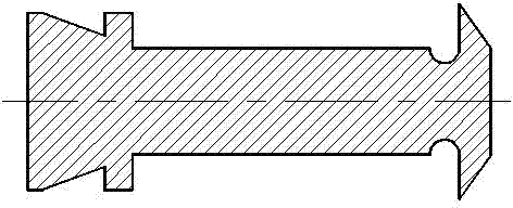
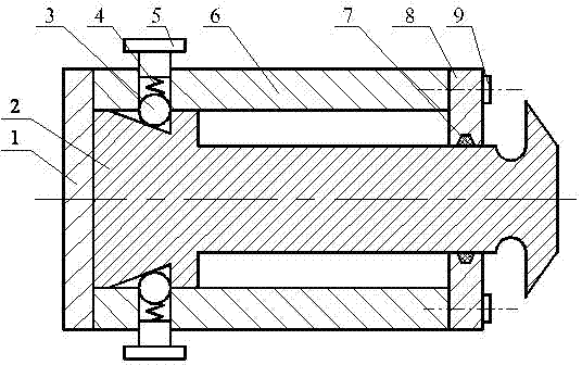
[0012] see figure 1 , weld the bottom plate 1 on the shell 6, install the sliding core 2 in the shell 6, fix the ball 3 on the metal spring 4, fix the other end of the metal spring 4 on the bolt 5, install the bolt 5 on the shell On the body 6, the sealing ring 7 is installed in the cover plate 8, and the cover plate 8 is fixed on the shell 6 with screws 9. The overspeed sensor for the mine car is installed on the rotating shaft, and the sliding core 2 tends to move forward along the axial direction under the centrifugal force, but the ball 3 prevents the sliding core 2 from moving under the action of the metal spring 4. When the rotation speed of the mechanical overspeed sensing mechanism increases gradually, the centrifugal force of the sliding core 2 increases gradually, and the contact force between the sliding core 2 and the ball 3 increases. Since the matching part of the sliding core 2 and the ball 3 is a wedge-shaped groove, Therefore, the component force of the contact
Embodiment 2
[0014] see figure 1 , weld the bottom plate 1 on the housing 6, install the sliding core 2 in the housing 6, fix the ball 3 on the rubber spring 4, fix the other end of the rubber spring 4 on the bolt 5, install the bolt 5 on the housing On the body 6, the sealing ring 7 is installed in the cover plate 8, and the cover plate 8 is fixed on the shell 6 with screws 9. The overspeed sensor for the mine car is installed on the rotating shaft, and the sliding core 2 tends to move forward along the axial direction under the centrifugal force, but the ball 3 prevents the sliding core 2 from moving under the action of the rubber spring 4. When the rotation speed of the mechanical overspeed sensing mechanism increases gradually, the centrifugal force of the sliding core 2 increases gradually, and the contact force between the sliding core 2 and the ball 3 increases. Since the matching part of the sliding core 2 and the ball 3 is a wedge-shaped groove, Therefore, the component force of the
PUM
 Abstract
Description
Claims
Application Information
 - R&D Engineer
- R&D Manager
- IP Professional
- Industry Leading Data Capabilities
- Powerful AI technology
- Patent DNA Extraction
Browse by: Latest US Patents, China's latest patents, Technical Efficacy Thesaurus, Application Domain, Technology Topic.
© 2024 PatSnap. All rights reserved.Legal|Privacy policy|Modern Slavery Act Transparency Statement|Sitemap