Electric potentiall treatment device

A potential therapy and high potential technology, applied in the field of potential therapy devices, can solve the problems of waste, trouble, complicated structure of the potential therapy device, etc., and achieve the effect of ensuring safety and simplifying the structure

Active Publication Date: 2012-05-23
HAKUJU INST FOR HEALTH SCI
View PDF3 Cites 0 Cited by
  • Summary
  • Abstract
  • Description
  • Claims
  • Application Information

AI Technical Summary

Benefits of technology

This technology allows for safer treatments during physical therapies without causing electrical hazards or damaging healthy tissues. It involves controlling the amount of energy delivered into specific parts of the body based upon their position relative to each other's location within the field space around them. By doing this, the patient receives more precise levels of therapeutic pressure compared to traditional methods where they must stay still longer after sessions. Additionally, there may also include sensors placed under different temperatures to monitor how well the heater works effectively (or prevent damage). Overall, these technical features help reduce harm caused by prolonged exposure to coldness and improves overall outcomes such as reduced pain relief time postoperative recovery periods.

Problems solved by technology

This patented technology describes how electrical therapeutic devices can help people relax or treat diseases more effectively without causing harm themselves through physical contact between them and their own bodies during use. Current methods involve placing the user undergoing treatment near a conductive plate called a seat where they sit down for easy access. When this positioned improves blood circulation, the users get less pain than other locations because they don’t have any direct contacts like those found outside. Additionally, these techniques require the user to lie still further towards the ground before getting used again.

Method used


Image

  • Electric potentiall treatment device
  • Electric potentiall treatment device
  • Electric potentiall treatment device

Examples


Embodiment approach 1

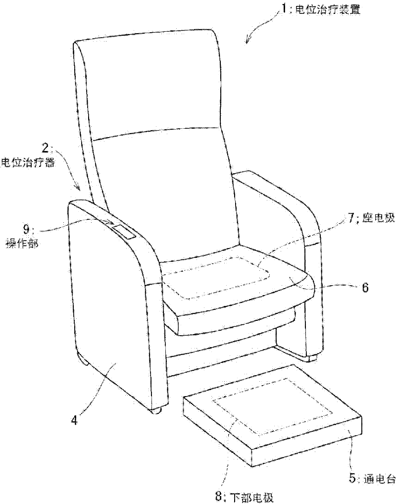
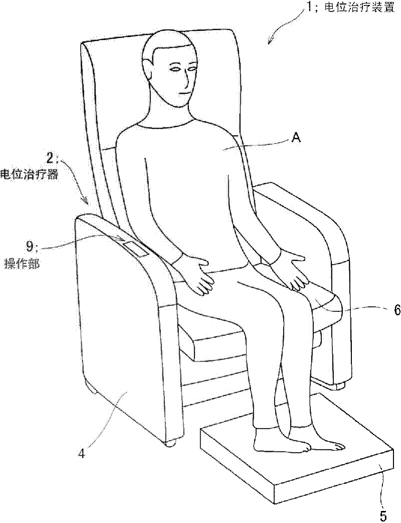
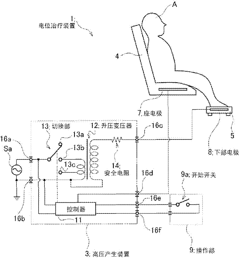
[0037] figure 1 It is a perspective view showing the structure of the electric potential therapy device according to Embodiment 1 of the present invention, figure 2 It is a figure showing the structure of this electric potential therapy apparatus, and it is a perspective view of the state of the person to be treated sitting on a chair, image 3 is a circuit diagram for explaining the structure of the potential therapy device, Figure 4 It is a processing sequence diagram for explaining the operation of the electric potential therapy device.

[0038] Such as Figure 1 to Figure 3 As shown, the potential therapy device 1 according to Embodiment 1 includes a potential therapy device 2 and a high voltage generator 3 . The electric potential therapy device 2 has a chair 4 on which the person to be treated A sits, and a conduction stand 5 on which the feet of the person to be treated A are placed. The chair 4 is covered with an insulator, and a seat electrode 7 is embedded in the

Embodiment approach 2

[0053] Figure 5 It is a perspective view showing the configuration of a potential therapy device according to Embodiment 2 of the present invention, Figure 6 and Figure 7 is an explanatory diagram for explaining the structure and function of the electric potential therapy device, Figure 8 is a circuit diagram for explaining the structure of the high voltage generating device of the electric potential therapy device, Figure 9 It is a processing sequence diagram for explaining the operation of the electric potential therapy device.

[0054] Such as Figure 5 to Figure 8 As shown, the potential therapy device 17 according to Embodiment 2 includes a potential therapy device 18 and a high voltage generator 19 . The electric potential therapy device 18 has a chair 20 on which the person to be treated B sits, a conduction stand 21 on which the feet of the person to be treated B are placed, and a head cover 22 . The chair 20 is covered with an insulator, and a seat electrode 24


PUM


Abstract

The configuration is made simpler, and deterioration is prevented. At first, a pilot potential with no risk of electrical shock is applied to an energization base (5), the induced current in a seat electrode (7) is measured, whether or not a high voltage can be applied is determined by changes in a current value associated with the seating of a patient (A) to be treated on a chair (4), and when determined that the high voltage can be applied, a therapeutic high voltage is applied to the energization base (5). In addition, whether or not output block is necessary is determined by changes in a current value associated with the separation of the patient (A) to be treated from the chair (4), and when determined that the output block is necessary, the output is blocked.

Description


Claims


Application Information

Patent Timeline
Owner HAKUJU INST FOR HEALTH SCI
Why Eureka
Try Eureka