Switchgear
A switch and fixed-side technology, applied in the direction of electric switches, grounding switches, switchgear, etc., can solve the problems of complex electrode structure and difficult assembly operations
- Summary
- Abstract
- Description
- Claims
- Application Information
AI Technical Summary
Problems solved by technology
Method used
Image


Examples
Embodiment 1
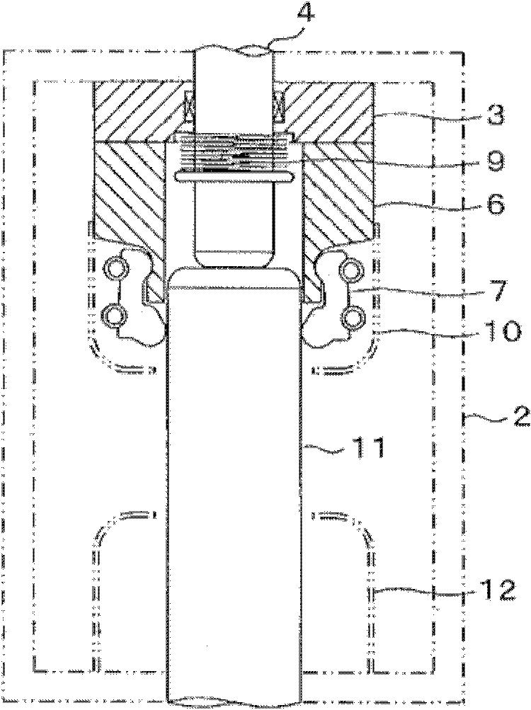
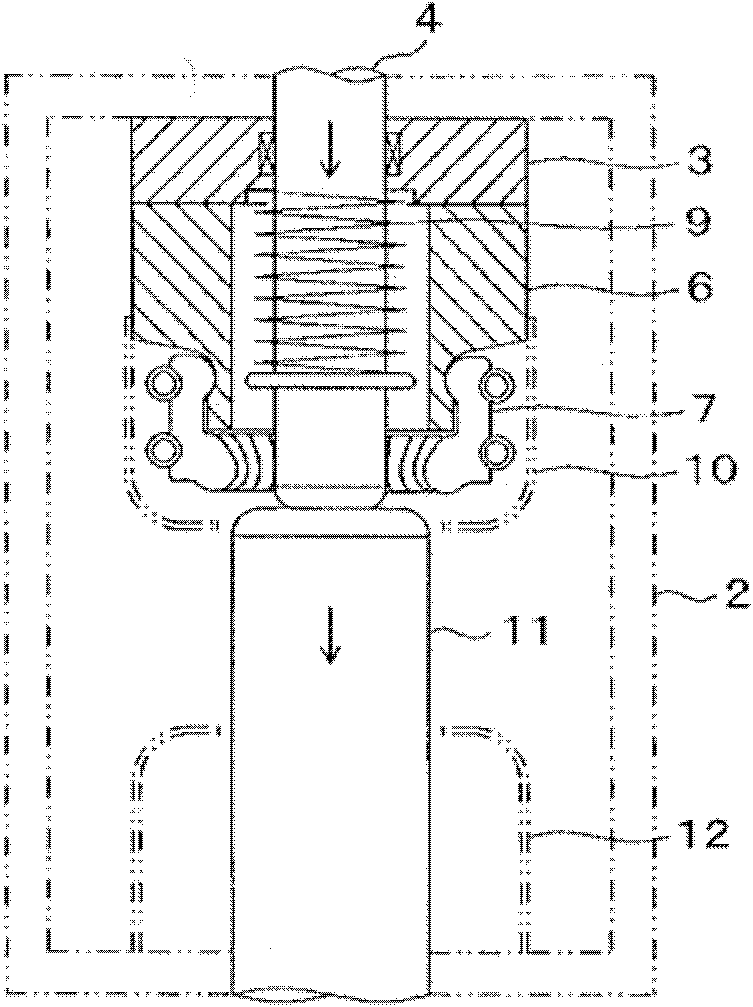
[0016] First refer to figure 1 , Figure 2A and Figure 2B The switch of Embodiment 1 of the present invention will be described. figure 1 It is a sectional view of main parts showing the structure of the switch according to Embodiment 1 of the present invention, Figure 2A It is a sectional view illustrating the operation of the switch according to Embodiment 1 of the present invention. In addition, in each figure, the main structure of a switch is shown by a solid line, and the incidental structure is shown by a two-dot chain.
[0017] Such as figure 1 As shown, the switch includes a fixed-side electrode part 1a on the upper part of the figure and a movable-side electrode part 1b on the lower part of the figure, which are arranged opposite to the axial direction of the fixed-side electrode part 1a. Insulated container 2.
[0018] In the fixed-side electrode portion 1 a , an annular fixed-side conductor 3 forming one current path is fixed to one end of the insulating case
Embodiment 2
[0030] Then refer to image 3 A switch according to Embodiment 2 of the present invention will be described. image 3 It is a sectional view of main parts showing the structure of the switch according to Embodiment 2 of the present invention. In addition, this second embodiment differs from the first embodiment in that an insulating coating is provided on the outer peripheral side of the fixed-side electrode shaft. exist image 3 The same reference numerals are assigned to the same structural parts as those in Embodiment 1, and detailed description thereof will be omitted.
[0031] Such as image 3 As shown, an insulating coating 14 is provided on the outer peripheral side surface between the spring seat plate 8 and the tip of the fixed-side electrode shaft 4 . The insulating coating 14 is made of, for example, a fluorine-containing resin having a thickness of about 1 mm and having heat resistance.
[0032] According to the switch of the above-mentioned embodiment 2, in addi
Embodiment 3
[0034] Then refer to Figure 4 A switch according to Embodiment 3 of the present invention will be described. Figure 4 It is a cross-sectional view of main parts showing the structure of the switch according to Embodiment 3 of the present invention. In addition, this Example 3 differs from Example 2 in that an arc-resistant member is provided at the tip of the electrode shaft. exist Figure 4 In , the same reference numerals are assigned to the same structural parts as those in Embodiment 2, and detailed description thereof will be omitted.
[0035] Such as Figure 4 As shown, arc-resistant members 15 made of, for example, a tungsten / copper alloy are respectively provided at the tips of the fixed-side electrode shaft 4 and the movable-side electrode shaft 11 . Furthermore, the arc-resistant member 15 has a cross-sectional semicircular shape with a protruding center. In addition, arc resistance can be provided by providing the arc-resistant member 15 on at least one of the
PUM
 Abstract
Description
Claims
Application Information
 - R&D Engineer
- R&D Manager
- IP Professional
- Industry Leading Data Capabilities
- Powerful AI technology
- Patent DNA Extraction
Browse by: Latest US Patents, China's latest patents, Technical Efficacy Thesaurus, Application Domain, Technology Topic.
© 2024 PatSnap. All rights reserved.Legal|Privacy policy|Modern Slavery Act Transparency Statement|Sitemap