Torch component of plastic rolling machine

A rotomolding machine and torch technology

Inactive Publication Date: 2012-12-19
海门市知舟工业设计有限公司
View PDF6 Cites 0 Cited by
  • Summary
  • Abstract
  • Description
  • Claims
  • Application Information

AI Technical Summary

Benefits of technology

The technical effects are that by adding an injector system where there's more space between two parts (the part being filled) than before they meet at one end or another, it makes the process quicker for natural gasses passing over them while also allowing better control on how much energy flows into each section during filling compared to previous designs. This results in improved production rates without sacrificing productivity.

Problems solved by technology

This patented technical problem addressed in this patents relates to improving the efficiency of an injector used for supplying liquid (natural gas) into a rotating mold during manufacturing processes such as rotational casting machines or similar equipment.

Method used


Image

  • Torch component of plastic rolling machine
  • Torch component of plastic rolling machine
  • Torch component of plastic rolling machine

Examples


Embodiment Construction

[0017] The present invention will be described in detail below in conjunction with the implementations shown in the drawings, but it should be noted that these implementations are not limitations of the present invention, and those of ordinary skill in the art based on the functions, methods, or structural changes made by these implementations Equivalent transformations or substitutions all fall within the protection scope of the present invention.

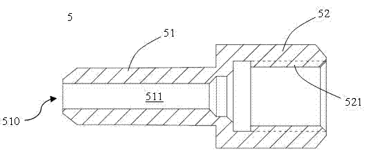
[0018] Please refer to figure 1 as shown, figure 1 It is a structural schematic diagram of a rotational molding machine torch assembly in the prior art. In this embodiment, the rotational molding machine torch assembly 100 includes:

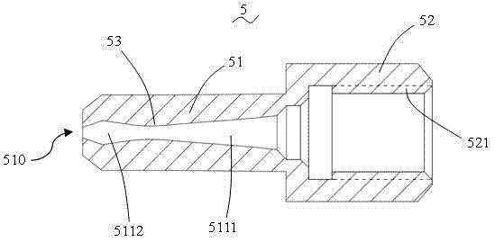
[0019] The nozzle 5 and the gas pipe 4 , the nozzle 5 has a spraying part 51 and a connecting part 52 ; the spraying part 51 has a nozzle 510 at one end, and the other end communicates with the connecting part 52 . ginseng image 3 As shown, the injection part 51 is provided with an injection channe


PUM


Abstract

The invention provides a torch component of a plastic rolling machine. The torch component comprises a nozzle and a gas tube. The nozzle is provided with an injection portion and a connection portion, a nozzle orifice is arranged at one end of the injection portion, the other end of the injection portion is communicated with the connection portion, the injection portion is provided with an injection passage along the axial direction of the injection portion and is communicated with the gas tube through the connection portion, a necking portion is disposed in the injection passage, and the diameter of the injection passage is increased gradually from the necking portion to the connection portion, and is particularly increased first and then reduced from the necking portion to the nozzle orifice. When flowing through the injection passage, natural gas can be compressed by the necking portion, and flow rate of the natural gas is increased, so that flame injection speed is increased, heating efficiency to moulds is increased, and quality of plastic rolled products is improved.

Description


Claims


Application Information

Patent Timeline
Owner 海门市知舟工业设计有限公司
Why Eureka
Try Eureka