Temperature control device and temperature control method thereof

A temperature control device and temperature control technology, applied in the direction of refrigeration safety arrangements, refrigeration components, refrigerators, etc., can solve the problems of control system complexity, high exhaust temperature, increased cost, etc., and achieve the effect of avoiding control complexity

Active Publication Date: 2013-03-06
SHANGHAI MICRO ELECTRONICS EQUIP (GRP) CO LTD
View PDF7 Cites 9 Cited by
  • Summary
  • Abstract
  • Description
  • Claims
  • Application Information

AI Technical Summary

Problems solved by technology

However, this will cause the compressor discharge temperature to be too high, so the electronic expansion valve of the condensing bypass circuit needs to be opened to a certain degree.
[0005] Although this solves the above-ment

Method used


Image

  • Temperature control device and temperature control method thereof
  • Temperature control device and temperature control method thereof
  • Temperature control device and temperature control method thereof

Examples


Embodiment Construction

[0034] In order to better understand the technical content of the present invention, specific embodiments are given together with the attached drawings for description as follows.

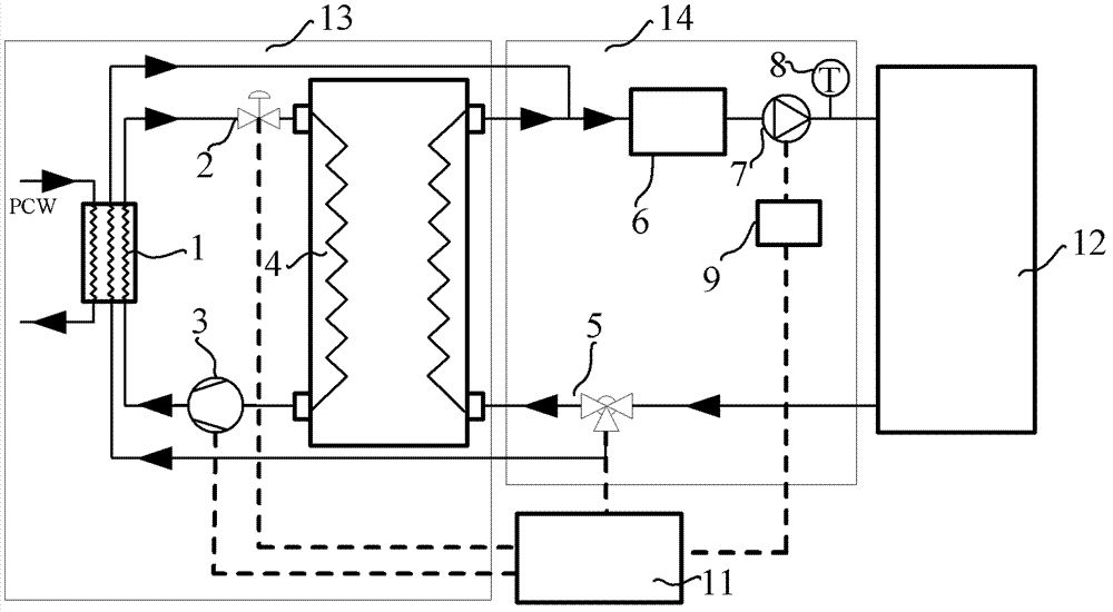
[0035] Please see figure 1 , figure 1 Shown is a functional block diagram of the temperature control device of the first embodiment of the present invention.

[0036] The present invention proposes a temperature control device for controlling the temperature of the circulating fluid flowing through the external device 12 .

[0037] The temperature control device includes a refrigeration device 13 , a circulating liquid circuit unit 14 and a controller 11 .

[0038] The refrigeration device 13 mainly includes a condensing device 1 , an expansion device 2 , a compressor 3 and an evaporating device 4 . The condensing device 1 can not only take away the condensation heat of the evaporating device 4 , but also take away the heat load transmitted from the external device 12 to the circulating fluid. The


PUM


Abstract

The invention provides a temperature control device and a temperature control method. The temperature control device and the temperature control method are used for controlling the temperature of circulating liquid flowing through an external device. The temperature control device comprises a refrigerating device, a circulating liquid circuit unit and a controller. The refrigerating device comprises an evaporating device and a condensing device. The circulating liquid circuit unit comprises an electric three-way valve and a temperature sensor. The circulating liquid flows into the evaporating device and the condensing device via the electric three-way valve. When the temperature sensor senses that the temperature of the circulating liquid is higher than a set value, the controller controls the electric three-way valve to increase the proportion of the circulating liquid flowing through the condensing device, and when the temperature of the circulating liquid is lower than the set value, the proportion of the circulating liquid flowing through the condensing device is reduced. The temperature control device and the temperature control method have the advantages that control complexity due to the fact that two bypass circuits are adopted in order to prevent excessively high exhaust temperature of a compressor is avoided, and the purpose of saving energy is achieved owing to the fact that a refrigerating system of the compressor is omitted.

Description


Claims


Application Information

Patent Timeline
Owner SHANGHAI MICRO ELECTRONICS EQUIP (GRP) CO LTD
Why Eureka
Try Eureka