Car door sill device filling gap of stopped layer

A technology of sills and gaps, applied in the field of elevators, can solve problems such as danger, trouble, and small rollers stuck, and achieve the effects of simple structure, convenient installation, and low cost

Inactive Publication Date: 2013-03-27
MITSUBISHI ELECTRIC SHANGHAI ELECTRIC ELEVATOR
View PDF3 Cites 7 Cited by
  • Summary
  • Abstract
  • Description
  • Claims
  • Application Information

AI Technical Summary

Benefits of technology

This new design uses an extendible security touch screen for cars' doors instead of being fixed at one end during use. It doesn’t interfere with regular operation but it works well if there are no passenger inside on top of this device.

Problems solved by technology

The current elevating systems have gaps that allow objects from one part of the system to get inside while another area falls off during operation. This can lead to damage when trying to move around on an escalation floor without being able to access important parts within it.

Method used


Image

  • Car door sill device filling gap of stopped layer
  • Car door sill device filling gap of stopped layer
  • Car door sill device filling gap of stopped layer

Examples


Embodiment Construction

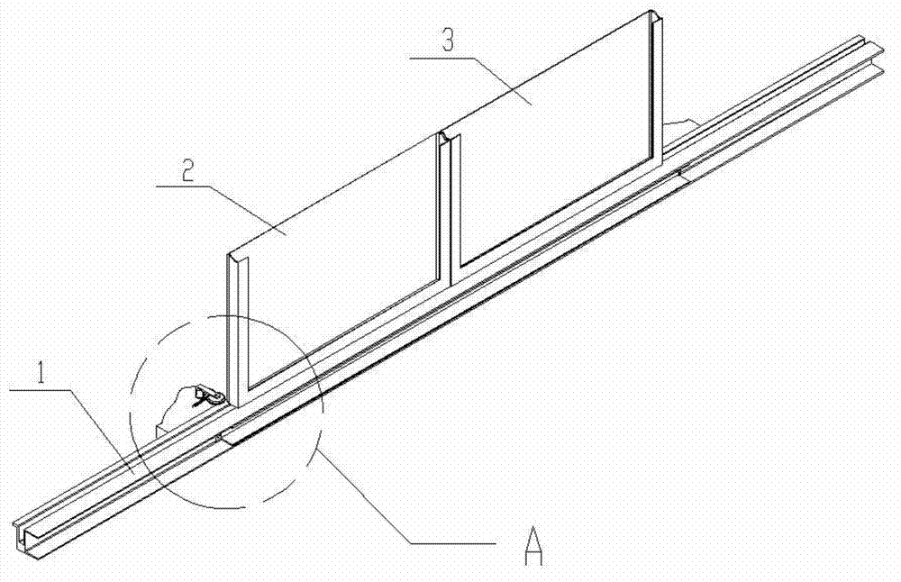
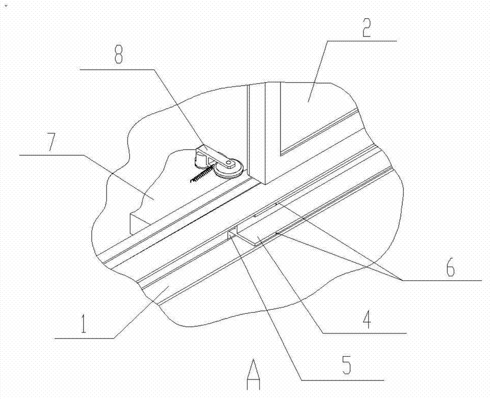
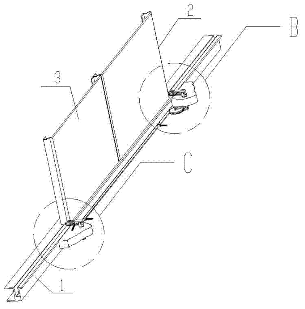
[0033] Such as Figures 1 to 5 As shown, a car door sill device for filling the landing gap according to the present invention includes a car sill 1 with a gap 5, a retractable safety touch panel 4, and a roller assembly that can trigger the expansion and contraction of the safety touch panel 4 8.

[0034] The car side of the safety contact plate is connected with the car floor assembly or the car outer side 7 through a spring 15 .

[0035] Such as Figure 4 , 5 As shown, the roller assembly 8 is composed of two rollers 10, 11, two roller brackets 12, 13, a main shaft 14, a spring 9 and supporting roller shafts and bushings and other accessories.

[0036] The rollers 10 , 11 are mounted on one end of the roller brackets 12 , 13 respectively, and the other ends of the roller brackets 12 , 13 are connected to the end of the main shaft 14 . One end of the spring 9 is connected with the upper roller bracket 12, and the other end is connected with the car bottom assembly or the ou


PUM


Abstract

The invention discloses a car door device used for filling a gap of a stopped layer. The car door device used for filling the gap of the stopped layer comprises a car door sill provided with a gap, a telescopic safety shoe and a roller assembly which can trigger the safety shoe to be telescopic. The car door device disclosed by the invention fills the gap of the sill, so that passengers can come in and go out of a lift car safely. The probability that small articles carried by the passengers who take a lift fall into the gap of the sill can be effectively reduced, and a risk that wheels of a baby carriage or wheelchair are blocked in the gap of the sill can be avoided.

Description


Claims


Application Information

Patent Timeline
Owner MITSUBISHI ELECTRIC SHANGHAI ELECTRIC ELEVATOR
Why Eureka
Try Eureka