Positioning turning device

A rotary shaft and rotary disc technology, applied in the field of multi-station processing devices, can solve the problems of high investment cost, large floor space, and adding manipulators, etc., and achieve the effect of small floor space, compact structure, and high precision

Inactive Publication Date: 2013-04-03
安阳第二机床有限公司
View PDF5 Cites 1 Cited by
  • Summary
  • Abstract
  • Description
  • Claims
  • Application Information

AI Technical Summary

Problems solved by technology

Apparently, Option 1 and Option 2 not only occupy a large space, but also cost a lot
As for the use of machining centers, although the accuracy is easy to guarantee and the floor space is small, the input cost is very high.
Especi

Method used


Image

  • Positioning turning device
  • Positioning turning device
  • Positioning turning device

Examples


Embodiment 1

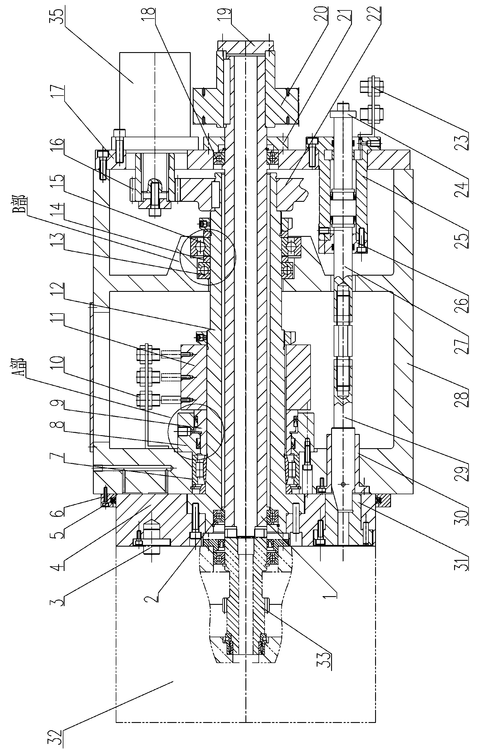
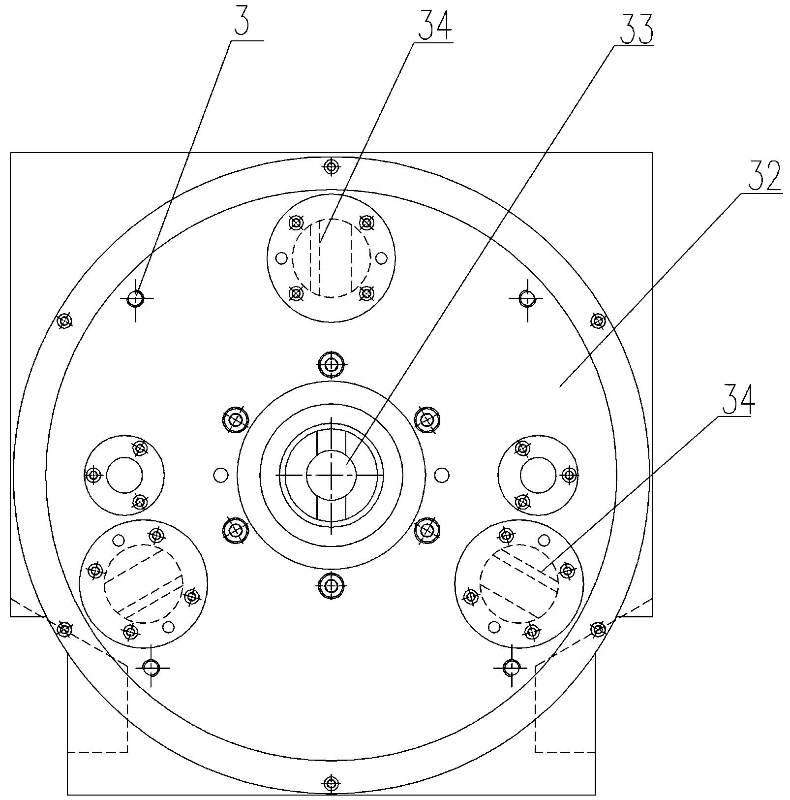
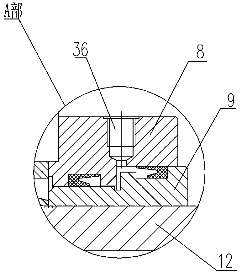
[0017] Embodiment 1: see Figure 1-Figure 4 Positioning rotary device in. The drive shaft 1 is installed on the rotary shaft 12 and the rear cover 17 of the box with two ball bearings 2, 18. The rear end of the drive shaft 1 is equipped with a toothed belt pulley 20 powered by a driving motor, and the front end is connected with the keyway on the rear end surface of the drive shaft of the headstock. Connected to drive the headstock spindle to rotate for processing.

[0018] The back cover 17 of the box body is fixed on the box body 28 with a screw cylindrical pin, and a bolt oil cylinder 25 and a hydraulic motor 35 are installed on it through a positioning bolt. The driving gear 16 is connected with the hydraulic motor 35 by a spline, and the driving gear 16 drives the driven gear 22, the driven gear 22 is connected with the rotary shaft 12 with a key, thereby driving the rotary shaft 12 to rotate, and the rotary disc 4 is connected and fixed with the rotary shaft 12 with screws

Embodiment 2

[0021] Embodiment 2: The accompanying drawings are not drawn, and the content is basically the same as Embodiment 1, and the similarities will not be repeated. The difference is that six spindles are evenly distributed on the end surface of the headstock, which is suitable for parts that need to be processed six times. When processing a station, the positioning rotary device drives the spindle box to rotate 60 degrees, and the latch mechanism is inserted into the positioning sleeve to realize positioning.


PUM


Abstract

The invention relates to a positioning turning device which drives in a hydraulic and mechanical combined mode and comprises a turning mechanism, a hydraulic locking releasing mechanism, a hydraulic positioning plug mechanism and a power driving mechanism, wherein a turning plate is driven by a hydraulic motor through a set of gears and is continuously turned along a same peripheral direction; when a signal is encountered, the turning is stopped, a plug cylinder is plugged, the turning plate is positioned, and then the turning plate is backward pulled and locked by a locking cylinder; and a power part transmits the power to a main bearing box which is used together with the power part through a driving shaft. The positioning turning device is used together with the main bearing box and is suitable for a special machine and an automatic moving line for repeatedly processing a same position on a workpiece in different processes. The positioning turning device has the advantages of compact structure, stability in moving, high precision, low cost and conveniences in operating and maintaining.

Description


Claims


Application Information

Patent Timeline
Owner 安阳第二机床有限公司
Why Eureka
Try Eureka