Clip for fastening surface skin material
A skin material and installation technology, which is applied in the field of fixtures for fixing and installation of skin materials, can solve the problems such as the difficulty of metal wire passing through, the obstruction of hooks and guide rods when they want to open, etc.
- Summary
- Abstract
- Description
- Claims
- Application Information
AI Technical Summary
Benefits of technology
Problems solved by technology
Method used
Image

Examples
no. 1 Embodiment approach
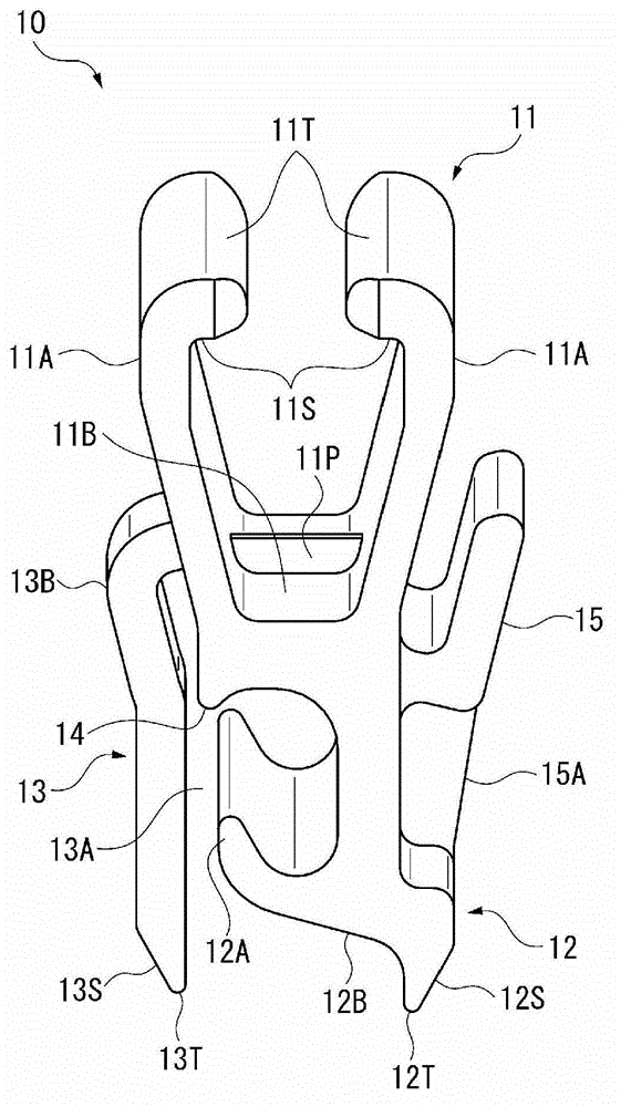
[0049] Figure 1 to Figure 7 The first embodiment of the jig for fixing and installing the surface material of the present invention is shown.
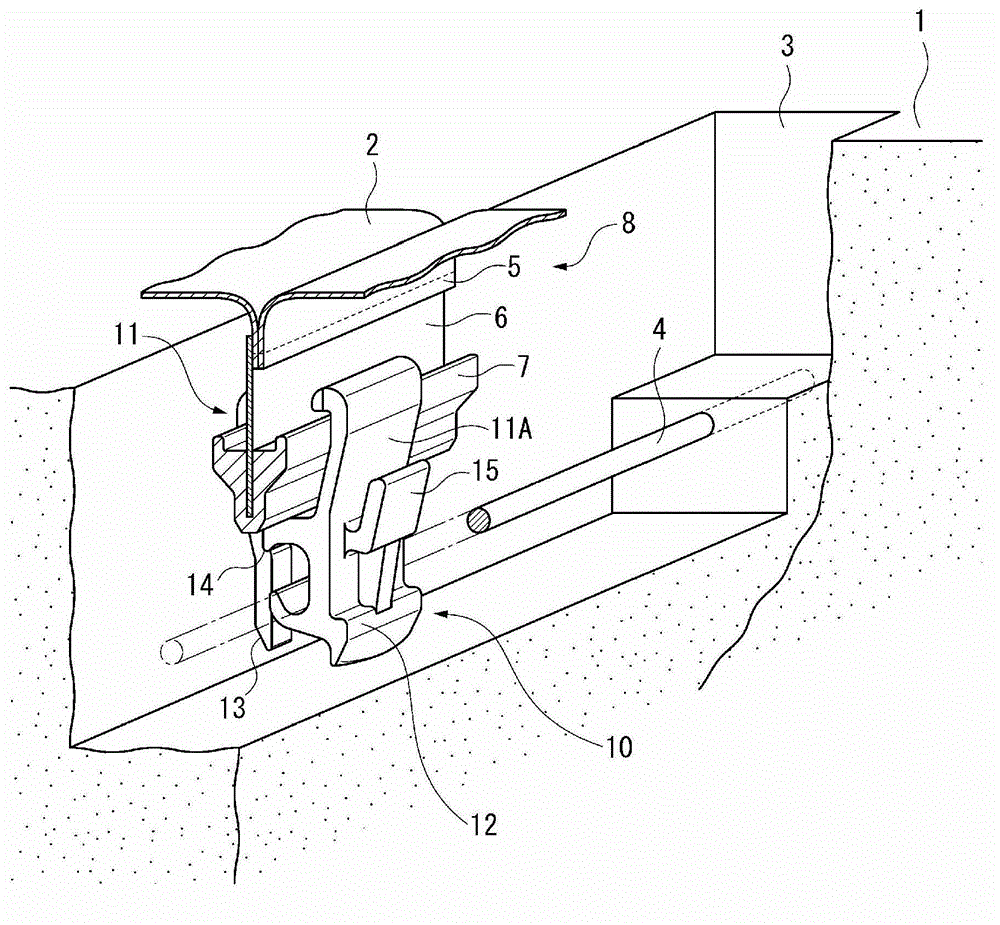
[0050] Such as figure 1 As shown, the jig 10 of this embodiment is used to hang two skin materials on the surface of the cushioning material 1 of the vehicle seat.
[0051]The shock absorber 1 is a synthetic resin molding such as foamed urethane molded into a seat shape. The buffer member 1 is formed with a groove 3 for fixing and installing the skin material, and a metal wire 4 is arranged in the groove 3 . The metal wire 4 is a wire rod made of metal, and the metal wire 4 can be embedded in the cushioning material 1 when it is molded.
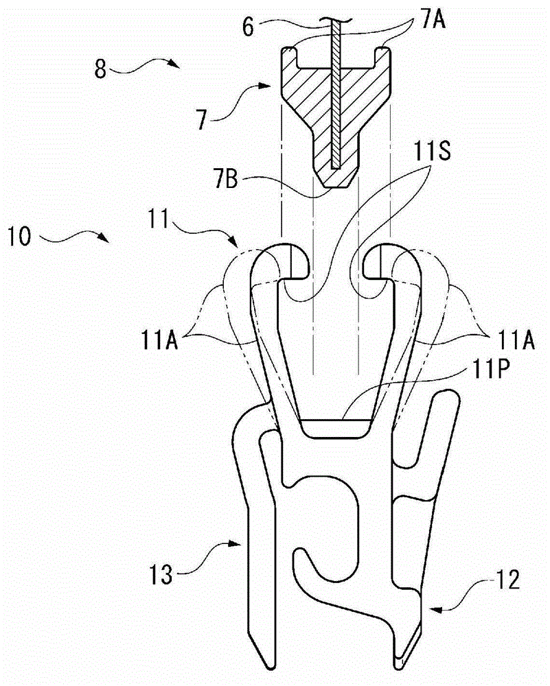
[0052] The skin material 2 is a synthetic resin woven sheet or the like covering the surface of the cushioning material 1 , and the skin material 2 has a sewn portion 5 at a portion corresponding to the groove 3 of the cushioning material 1 . The end edges of the pair of sheets are folded toward the
no. 2 Embodiment approach
[0100] Figure 8 The second embodiment of the present invention is shown.
[0101] The jig 10 of this embodiment is different from the above-mentioned first embodiment in the shape of the guide rod 13 . The rest of the structure is the same as that of the above-mentioned first embodiment, so redundant description will be omitted.
[0102] In the above-mentioned first embodiment, the guide rod 13 rises from the middle portion of the locking claw 11A of the jig head 11 , approaches the jig head 11 again through the bent portion 13B, and forms a straight line from the portion facing the guide protrusion 14 . The shape extends toward the front end portion 13T.
[0103] On the other hand, the guide rod 13 of the present embodiment rises obliquely from the base end of the locking claw 11A of the jig head 11, that is, near the jig head base 11B, and the portion that stands up by omitting the bending portion 13B immediately faces the front end portion 13T. linear extension.
[0104]
no. 3 Embodiment approach
[0106] Figure 9 The third embodiment of the present invention is shown.
[0107] The jig 10 of this embodiment differs from the above-described first embodiment in the shapes of the guide rod 13 , the locking claw 11A on the side of the guide rod 13 , and the jig head base 11B. The rest of the structure is the same as that of the above-mentioned first embodiment, so redundant description will be omitted.
[0108] In this embodiment, a bent portion 11C is formed on the base end side of one locking claw 11A of the jig head 11 . The portion of the jig head base 11B on the side of the guide bar 13 is shortened by the amount of displacement due to the presence of the bent portion 11C. The guide rod 13 is the same as the above-mentioned second embodiment, and the curved portion 13B is omitted. A portion of the guide rod 13 connected to the locking claw 11A is formed to have the same curvature as the curved portion 11C.
[0109] Also in this embodiment, the same effect as that of t
PUM
 Abstract
Description
Claims
Application Information
 - R&D Engineer
- R&D Manager
- IP Professional
- Industry Leading Data Capabilities
- Powerful AI technology
- Patent DNA Extraction
Browse by: Latest US Patents, China's latest patents, Technical Efficacy Thesaurus, Application Domain, Technology Topic.
© 2024 PatSnap. All rights reserved.Legal|Privacy policy|Modern Slavery Act Transparency Statement|Sitemap