Milling cutter guide fixing device

A technology for fixing devices and milling cutters, which is applied to milling machine equipment, milling machine equipment details, metal processing equipment, etc., can solve problems such as poor processing quality, reduced work efficiency, and hidden dangers of production safety, so as to ensure a safe operating environment and improve work efficiency. Efficiency, the effect of reducing production costs

Inactive Publication Date: 2013-06-26
乳山市黄海汽车配件有限公司
View PDF0 Cites 0 Cited by
  • Summary
  • Abstract
  • Description
  • Claims
  • Application Information

AI Technical Summary

Problems solved by technology

[0002] We know that at present, when milling the connecting rod, due to the special processing position, the tool rod needs to be lengthened, so that during the tool cleaning process, the tool rod shakes seriously due to the r

Method used


Image

  • Milling cutter guide fixing device

Examples


Embodiment Construction

[0008] The present invention will be further described below in conjunction with accompanying drawing:

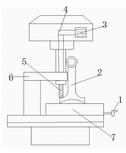
[0009] Such as figure 1 As shown, the present invention relates to a milling cutter guiding and fixing device, which is provided with a motor 3, a belt 4, a milling cutter 5, a guiding and fixing block 6, a workbench 7, a connecting rod 2, and a handle 1, and is characterized in that: the motor The transmission shaft on the 3 is connected with the rotating shaft of the milling cutter 5 through the belt 4, and the middle part of the milling cutter 5 is provided with a guide fixed block 6, and the workbench 7 is below the milling cutter 5, and the connecting rod 2 is fixedly installed on the workbench 7, and the working One side of the platform 7 is provided with a handle 1 .

[0010] When the present invention is used, firstly, the milling cutter is fixedly installed according to the requirements of milling processing, and then the guide fixing block is added to adjust the


PUM


Abstract

The invention relates to a milling cutter guide fixing device which is provided with a motor, a belt, a milling cutter, a guide fixing block, a working table, a connecting rod and a handle. The milling cutter guide fixing device is characterized in that a transmission shaft on the motor is connected with a rotating shaft of the milling cutter through the belt; the guide fixing block is arranged at the middle part of the milling cutter; the working table is arranged below the milling cutter; the connecting rod is fixedly mounted on the working table; and the handle is arranged at one side of the working table. The milling cutter guide fixing device provided by the invention is additionally provided with the guide fixing block, so that the severe shake of the milling cutter in a high-speed rotation process can be effectively avoided, the working efficiency is improved, the production cost is reduced, and the safe operation environment of workers can be ensured.

Description


Claims


Application Information

Patent Timeline
Owner 乳山市黄海汽车配件有限公司
Why Eureka
Try Eureka