Membrane type wall structure and application thereof
A membrane-type wall and tube-type technology, applied to building components, building structures, insulation, etc., can solve the problems that high-temperature materials cannot be effectively transported, effectively utilized, and waste heat cannot be implemented, so as to facilitate repair welding maintenance, Easy maintenance and fewer failures
- Summary
- Abstract
- Description
- Claims
- Application Information
AI Technical Summary
Problems solved by technology
Method used
Image
Examples
Embodiment 1
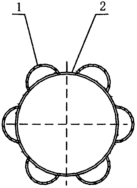
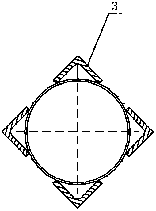
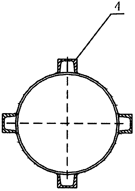
[0028] Such as Figure 1 to Figure 3 As shown, the membrane wall structure is formed by welding an arc tube structure 1 (radian<360°), an angle steel structure 3 or a channel steel structure 4 on the outer circumferential surface of a circular tube structure 2; the membrane wall structure The structure can be applied on high temperature feeding tube, high temperature ball mill and / or high temperature roller conveyor.
Embodiment 2
[0030] Such as Figure 4 to Figure 6 As shown, the membrane wall structure is formed by welding an arc tube structure 1 (radian <360°), an angle steel structure 3 or a channel steel structure 4 on multiple sides of a rectangular tube structure 5; the membrane wall structure can be Applied on high temperature feeding pipes and / or high temperature pneumatic conveyors.
Embodiment 3
[0032] Such as Figure 7 to Figure 9 As shown, the membrane wall structure is formed by welding an arc tube structure 1 (radian<360°), an angle steel structure 3 or a channel steel structure 4 on one side of a flat plate structure 6; the membrane wall structure is used as The trough of the scraper conveyor can constitute an environmentally friendly, energy-saving, and safe high-temperature scraper conveyor; Water can form a high temperature crusher. In addition, the membrane wall structure can form a new type of thermal insulation wall after being connected with a heat transfer medium as a thermal insulation panel for the wall.
PUM
| Property | Measurement | Unit |
|---|---|---|
| Radian | aaaaa | aaaaa |
Abstract
Description
Claims
Application Information
 - R&D Engineer
- R&D Manager
- IP Professional
- Industry Leading Data Capabilities
- Powerful AI technology
- Patent DNA Extraction
Browse by: Latest US Patents, China's latest patents, Technical Efficacy Thesaurus, Application Domain, Technology Topic.
© 2024 PatSnap. All rights reserved.Legal|Privacy policy|Modern Slavery Act Transparency Statement|Sitemap


