Novel electric quantity display circuit

A power display circuit and power indication technology, which is applied in the direction of digital variable/waveform display, measurement of electric variables, measurement of electricity, etc., can solve the problems of low display accuracy, complex power display circuit, and waste of power, so as to save system resources, The effect of high display precision and simple circuit structure

Active Publication Date: 2013-10-09
ZHEJIANG LINIX MOTOR
View PDF4 Cites 1 Cited by
  • Summary
  • Abstract
  • Description
  • Claims
  • Application Information

AI Technical Summary

Problems solved by technology

[0002] In recent years, electric vehicles have developed rapidly. For electric vehicles, the battery is the key technology. The indication of the remaining battery power tells the driver how far he can drive. The structure of the current power display circuit is relatively complicated, and the display accuracy is not high, which affects the electric vehicle. The driver's judgment leads to waste of electricity and wrong estimation of the driving distance

Method used


Image

  • Novel electric quantity display circuit
  • Novel electric quantity display circuit

Examples


Example Embodiment

[0013] The present invention will be further described below in conjunction with the drawings.

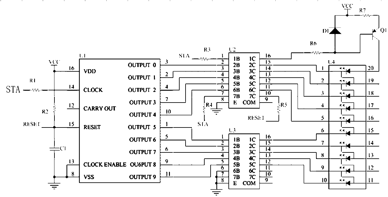
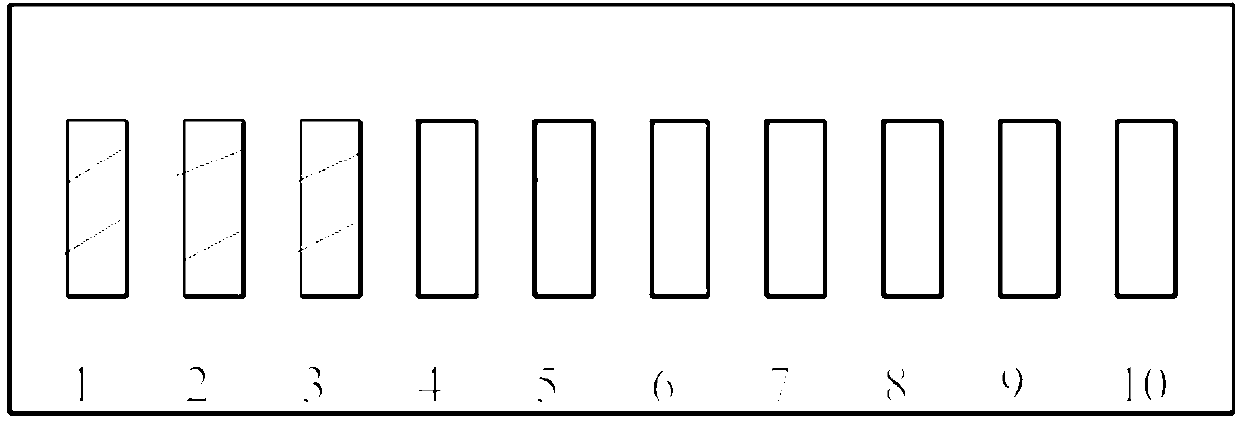
[0014] Such as figure 1 with 2 As shown, the new power display circuit of the present invention includes: a ten-digit shift counter U1, LED segment code driving circuits U2, U3, and a ten-digit segment code power indicator unit U4. STA is an input signal to control the power indicator, and STA passes all the way Resistor R1, input to pin 14 of U1, provides a clock signal for U1. The other two channels are input to U2 through resistors R3 and R4 to control the PNP transistor and provide a reset signal. RESET is the reset signal of U1, high level reset, this signal is provided by the 10 pin of U2. The ten shift counter U1 is a CD4017 chip, and the LED segment code drive circuits U2 and U3 are ULN2003 chips.

[0015] When the 15-pin RESET of U1 is high, the chip is reset. At this time, the output OUTPUT0~OUTPUT9 are cleared, and the output is low, and OUTPUT0 is high. When RESET is low


PUM


Abstract

The invention discloses a novel electric quantity display circuit which comprises a decade shift counter U1, a first LED segment code drive circuit U2, a second segment code drive circuit U3 and a decade segment code electric quality indicating unit U4. Five output end OUTPUT 0-OUTPUT 4 of the decade shift counter U1 are connected with the input end of the first LED segment code drive circuit U2, the other five output ends OUTPUT 5-OUTPUT 9 are connected with the input end of the second segment code drive circuit U3, and the output end of the first LED segment code drive circuit U2 and the output end of the second segment code drive circuit U3 are connected with the decade segment code electric quality indicating unit U4. According to the novel electric quantity display circuit, a coulometer indicates under the control of only one control signal STA, and therefore system resources are saved greatly. Further, the novel electric quantity display circuit is simple in structure and high in display accuracy.

Description


Claims


Application Information

Patent Timeline
Owner ZHEJIANG LINIX MOTOR
Why Eureka
Try Eureka