Nebulizer system and heater device used in said nebulizer system

A nebulizer and heater technology, applied in the direction of nebulizers, inhalers, respirators, etc. for treatment, can solve the problems of the nebulizer system toppling, the obstruction of the discharge pipe, and the contamination of the front end of the discharge pipe.

Active Publication Date: 2013-12-18
KOBAYASHI MEDICAL
View PDF9 Cites 4 Cited by
  • Summary
  • Abstract
  • Description
  • Claims
  • Application Information

AI Technical Summary

Benefits of technology

The technical effect described by this inventor's design allows for easy connections between different components like a liquid container or a heating element used with a spay gun. This makes removal from these parts easier without getting them out at their ends.

Problems solved by technology

This technical problem addressed in this patents relates to providing a stable and efficient way to provide medical gases through mist generators without being affected by external factors during their delivery process due to potential hazards caused by excessive condensate formation inside the generator itself.

Method used


Image

  • Nebulizer system and heater device used in said nebulizer system
  • Nebulizer system and heater device used in said nebulizer system
  • Nebulizer system and heater device used in said nebulizer system

Examples


Embodiment Construction

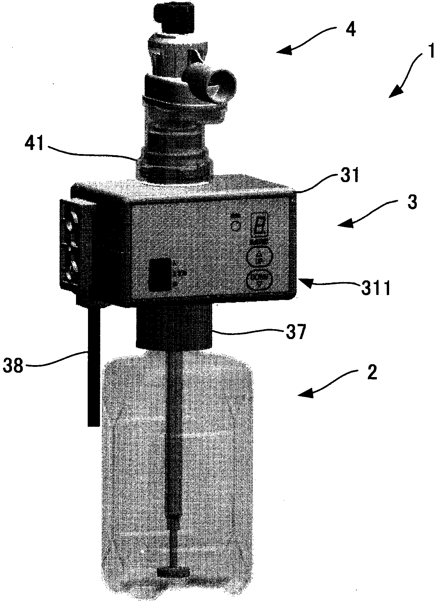
[0059] Next, a nebulizer system according to an embodiment of the present invention will be described with reference to the drawings. figure 1 It is a perspective view of the nebulizer system which concerns on one Embodiment of this invention.

[0060] Such as figure 1 As shown, the nebulizer system 1 of one embodiment of the present invention is, for example, a device for supplying humidified breathing gas, which includes: a bottle 2; a heater device 3 arranged on the upper part of the bottle 2; and a nebulizer connector 4. Set on the upper part of the heater device 3 .

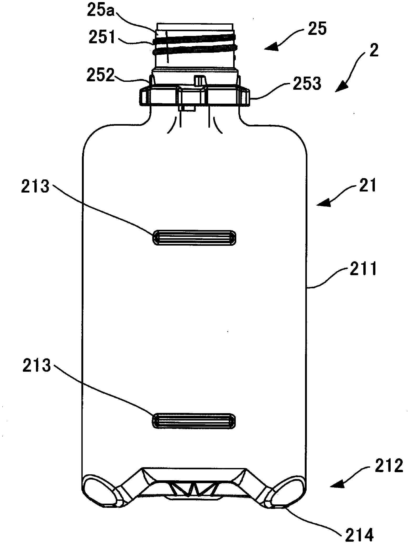
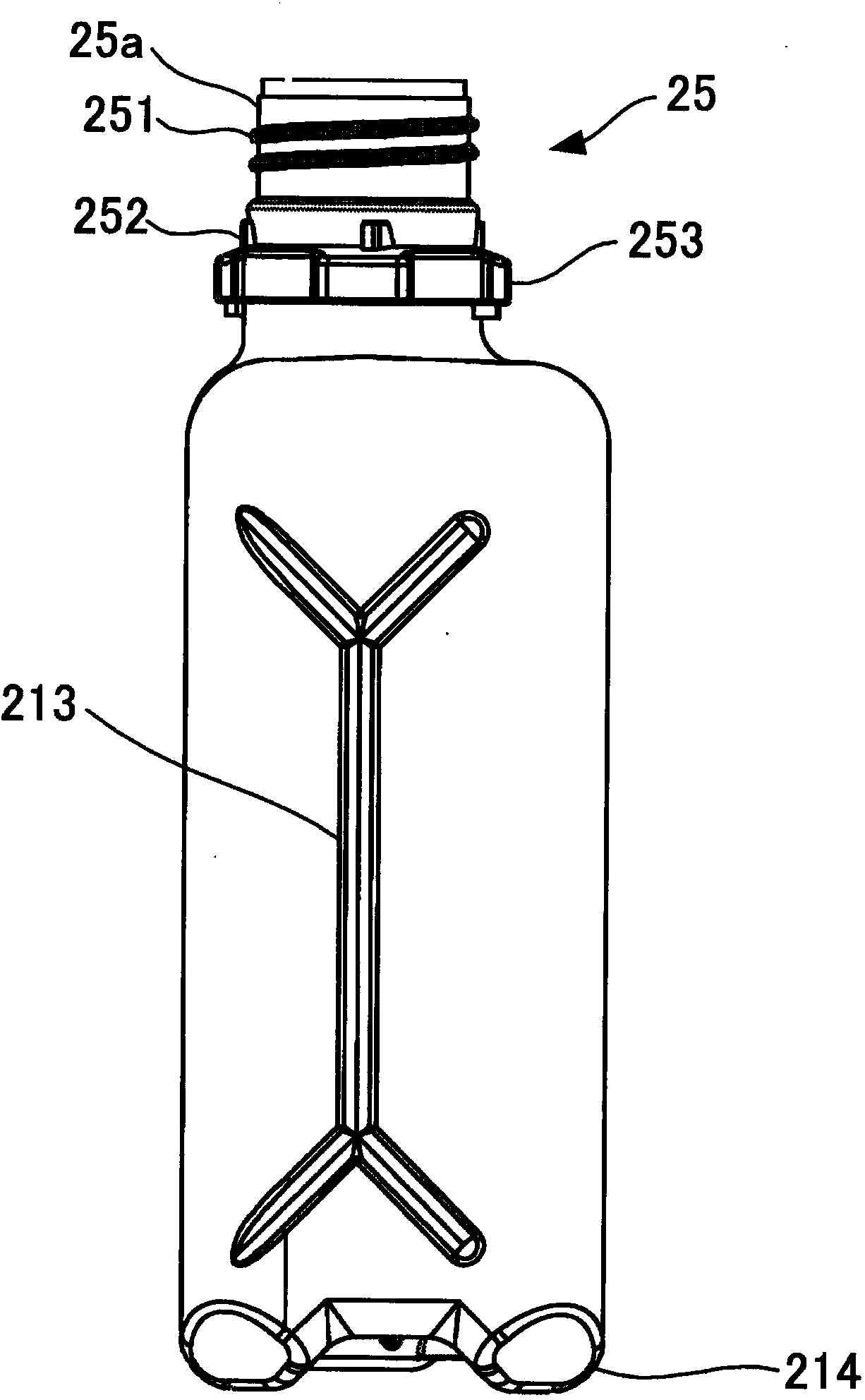
[0061] First, bottle 2 will be described. Such as Figure 2 to Figure 7 As shown, the bottle 2 is a container for internally storing liquids such as a solution containing medicaments or sterile water, purified water, distilled water, and physiological saline. The bottle 2 includes a bottle body 21 and a dipping tube 22 . in addition, figure 2 is the front view of bottle 2, image 3 It is the left side


PUM


Abstract

Provided are: a nebulizer system in which a bottle, heater device, and nebulizer adapter are easy to connect and there is no drain tube exposed to the outside and getting in the way; and a heater device suitable for use in said nebulizer system. Said nebulizer system (1) is provided with: a bottle (2), with a mouth (25) at the top thereof, in which a liquid is stored; a heater device (3) that can be connected to the mouth (25) of the bottle; and a nebulizer adapter (4) that can be connected to the heater device (3). The bottle (2) is provided with a dip tube (22) immersed in the liquid stored inside. With a space (226) provided at the top end of the dip tube (22), said space connecting the inside and outside of the bottle (2) through the mouth (25) thereof, the top end of the dip tube (22) is disposed inside the walls of the mouth (25) of the bottle. The nebulizer adapter (4) is provided with: a nozzle member (42) that has a nozzle (421) through which a gas is injected; and an aerosol-forming member (43) that is disposed at a location corresponding to the aforementioned nozzle (421) and that, by means of the stream of gas injected via the nozzle (421), suctions up the liquid in the bottle (2) via the dip tube (22) and the heater device (3) and turns said liquid into a fine aerosol. The following are provided inside the heater device (3): a channel (32), one end of which is connected to the top end of the dip tube (22) and the other end of which is connected to the aerosol-forming member (43); a heating unit (33) that heats said channel (32); and a drain tube (35), one end of which is disposed opposite the abovementioned space (226) and the other end of which returns liquid that was not aerosolized in the nebulizer adapter (4) back to the bottle (2).

Description


Claims


Application Information

Patent Timeline
Owner KOBAYASHI MEDICAL
Why Eureka
Try Eureka