Right angle type check valve

A one-way valve and right-angle technology, which is applied in the direction of control valves, valve devices, and functional valve types, can solve the problems of unstable and reliable work, complex structure of one-way valves, and inability to reverse flow, etc., and achieves simple structure and manufacturing The effect of low cost and small pressure loss

Inactive Publication Date: 2013-12-25
TAICANG KANGMAO ELECTRONICS
View PDF5 Cites 1 Cited by
  • Summary
  • Abstract
  • Description
  • Claims
  • Application Information

AI Technical Summary

Problems solved by technology

[0002] In order to meet the execution requirements of the hydraulic control mechanism, the reliability of the connection or disconnection of the directional control valve plays an important role. The check valve only allows the liquid flow to flow in one direction in the hydraulic system, and cannot flow in the opposite direction. The pe

Method used


Image

  • Right angle type check valve

Examples


Embodiment Construction

[0010] Below in conjunction with accompanying drawing, further illustrate the present invention.

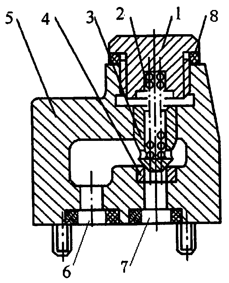
[0011] Such as figure 1 As shown, a right-angle check valve according to the present invention includes: an upper cover 1 , a spring 2 , a valve core 3 , a valve seat 4 , a valve body 5 , an inlet port 6 and an outlet port 7 .

[0012] The valve body 5 and the upper cover 1 are fastened, and the upper cover 1 is provided with a spring 2, and the left side of the spring 2 is provided with a valve core 3, and the valve core 3 and the valve seat 4 provided on the valve body 5 are offset, and the valve An inlet port 6 is provided on the left side of the seat 4 , and an outlet port 7 is provided below the valve body 5 .

[0013] The upper cover 1 and the spring 2 are fixedly connected, and a sealing ring 8 is provided in the middle of the upper cover 1 and the valve body 5, and the inlet port 6 and the outlet port 7 are communicated.

[0014] When the pressure oil enters the valve body


PUM


Abstract

The invention discloses a right angle type check valve, which comprises an upper cover, a spring, a valve core, a valve base, a valve body, an inlet end and an outlet end. The valve body and the upper cover are fastened; the spring is arranged in the upper cover; the valve core is arranged at the left side of the spring; the valve core is butted against the valve base arranged on the valve body; the inlet end is arranged at the left side of the valve base; the outlet end is arranged at the lower part of the valve body. The right angle type check valve controls the moving of the valve core, so that when liquid flows through, the pressure loss is little; when the liquid is reversely obstructed, the right angle type check valve is excellent in tightness, flexible in action, and stable and reliable in work; in addition, the right angle type check valve is simple in structure, and low in manufacturing cost.

Description


Claims


Application Information

Patent Timeline
Owner TAICANG KANGMAO ELECTRONICS
Why Eureka
Try Eureka