Offshore installation buffer device

A buffer device and buffer pad technology are applied in the field of offshore installation of buffer devices and soft landing systems, which can solve the problems of self-heavy wind turbine body, economic loss, wind turbine damage, etc., and achieve the effects of simple structure, smooth and soft landing, and high reliability.

Inactive Publication Date: 2018-06-08
TONGJI UNIV
View PDF9 Cites 1 Cited by
  • Summary
  • Abstract
  • Description
  • Claims
  • Application Information

AI Technical Summary

Benefits of technology

This patented technology improves upon existing systems for use in off shore installations where there may have sudden changes or fluctuating temperatures that could affect their performance. By allowing fluid from an accumulator back into the machine before it reaches its destination (the hub), this design allows more efficient operation over longer periods without losing power. It also provides flexibility in controlling how much liquid needs to flow out of the machine's tank while still maintaining good lubrication properties. Overall, these technical features improve efficiency and durability of off shore wind generators.

Problems solved by technology

This patented technical problem addressed in this patents describes how to prevent damaging or expensive equipment from being mounted near coastal areas where there could come into contact with seawater while installing offshoys without causing harmful effects such as water hammerings caused by wave action.

Method used


Image

  • Offshore installation buffer device

Examples


Embodiment

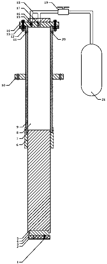
[0025] Example 1: see figure 1 , The buffer device installed on the offshore wind power generator includes three parts: a plunger assembly, a cylinder block assembly and an energy storage assembly. The cylinder assembly is sleeved on the outside of the plunger assembly to form an inner cavity, the plunger inner cavity communicates with the external oil pipe through the speed regulating valve and the one-way valve, and the energy storage assembly is connected to the oil pipeline in the cylinder through the interface of the upper end cover of the cylinder. The accumulator is charged with an inert gas (such as nitrogen) with a certain pressure.

[0026] Plunger assembly: Nylon pad and buffer pad are at the bottom of the structure, which is the contact surface with the offshore foundation platform; the buffer pad is connected to the lower end cover of the plunger through bolts; the lower end cover is welded to the inner surface of the cylinder to achieve closure; the two sides of the


PUM


Abstract

The invention relates to an offshore installation buffer device. The device is composed of a plunger assembly, a cylinder assembly and an energy storage assembly; the plunger assembly comprises a nylon pad, a cushion pad, a lower end cover and a plunger body; the cylinder assembly comprises a cylinder end cover, an oil passage pipe, a cylinder body, a cylinder flange, an end cover flange and an oil tube joint; a first cylinder end cover is welded on the lower end of the cylinder body, and the cylinder flange is arranged outside the cylinder body; a second cylinder end cover and an end cover flange are fixedly connected; a check valve and a speed adjustment valve are mounted on the second cylinder end cover; an oil nozzle and an air exhaust pressure measuring joint are mounted on the upperportion of the cylinder body; the oil tube joint is welded on the top of the end cover; the energy storage assembly comprises an oil pipe, a stop valve and an energy accumulator; the oil nozzle is connected to the energy accumulator through the oil pipe and the stop valve; the plunger body is located below the cylinder body, and a gap between the plunger body and the cylinder body forms a cylinderinner cavity. The device is designed according to environmental factors during installation of an offshore draught fan, has the advantages of being capable of buffer reset of multiple times in a short time, simple in structure and high in reliability, and can effectively ensure smooth soft landing of the offshore draught fan.

Description


Claims


Application Information

Patent Timeline
Owner TONGJI UNIV
Why Eureka
Try Eureka