Rotary support structure for sensors

A rotating support and sensor technology, applied in the direction of instruments, liquid level indicators, machines/engines, etc., can solve the problems of shaft deflection deviation, inaccurate measurement accuracy, and affecting the service life of Hall sensors, etc., to achieve structural stability and prolong use The effect of longevity

Inactive Publication Date: 2014-01-01
JIANGSU AOLIWEI SENSING TECH
View PDF5 Cites 1 Cited by
  • Summary
  • Abstract
  • Description
  • Claims
  • Application Information

AI Technical Summary

Problems solved by technology

At present, the fixing of the rotating shaft of the Hall sensor adopts positioning points symmetrically arranged on both sides of the shaft, and the connection position between the floating rod and the rotating shaft is also far away from the positioning point, which makes the driving position of the floating rod as the driving rod far away from the positioning point. As the posi

Method used


Image

  • Rotary support structure for sensors
  • Rotary support structure for sensors

Examples


Embodiment Construction

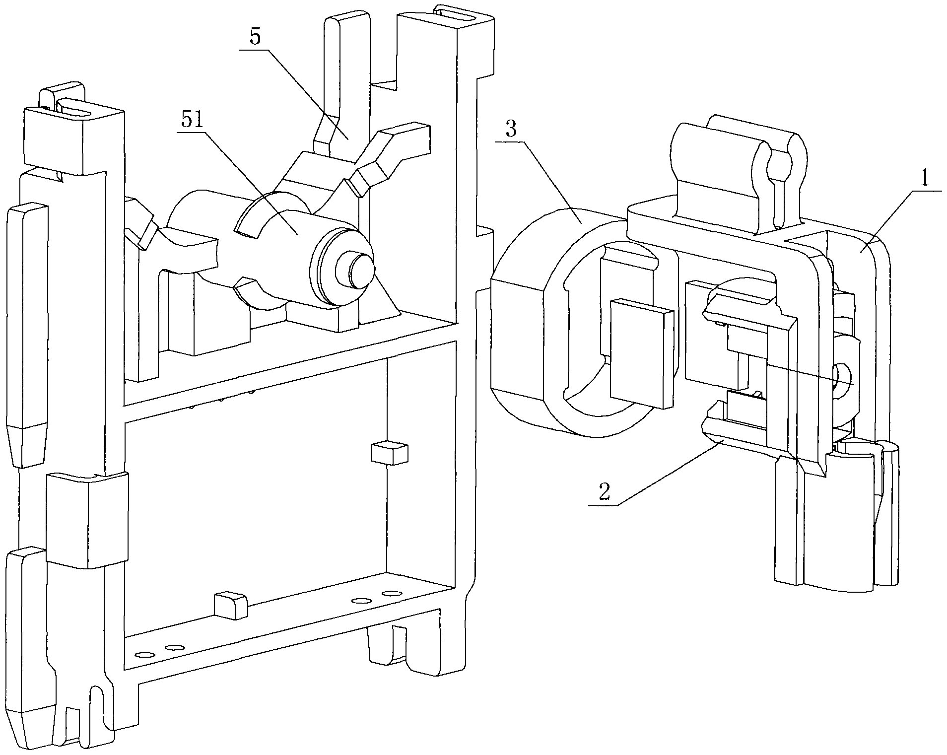
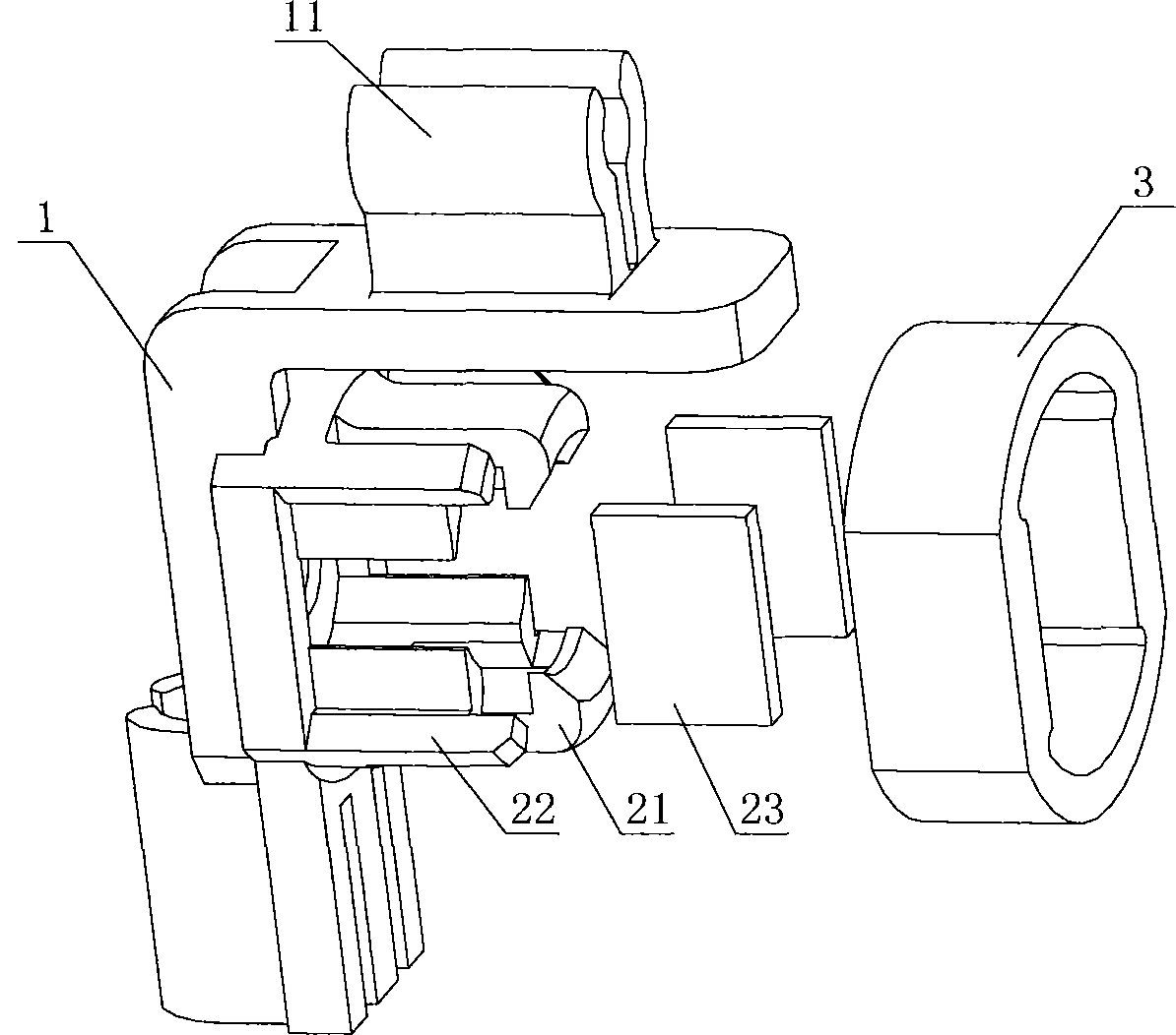
[0009] Such as Figure 1-2 As shown, the sensor rotation support structure described in the embodiment of the present invention is installed on the rotating shaft 51 of the Hall sensor 5, including the floating rod connecting part 1 connected with the floating rod, the rotating shaft connecting part 2 connected and positioned with the rotating shaft 51, A fixed sleeve 3 for positioning the auxiliary shaft connector 2, the floating rod connector 1 is connected to the rotating shaft connector 2, preferably, the floating rod connector 1 and the rotating shaft connector 2 are integrally formed; the floating rod connector 1 is L-shaped, and a floating rod connecting groove 11 is respectively provided on the top surface and the outer surface of the floating rod connecting part 1. The floating rod connecting groove 11 is an open structure, and the inner wall of the floating rod connecting groove 11 is cylindrical; The rotating shaft connector 2 is located on the inner surface of the flo


PUM


Abstract

The invention discloses a rotary support structure for sensors. The rotary support structure is installed on a rotary shaft of a Hall sensor. The rotary support structure is characterized by comprising a floating bar connector connected with a floating bar, a rotary shaft connector, and a fixing sleeve, wherein the rotary shaft connector connected with the rotary shaft is used for positioning and the fixing sleeve assists the rotary shaft connector in positioning. The floating bar connector is connected with the rotary shaft connector and is L shaped. The top and outside of the floating bar connector are provided with floating bar connecting channels. The rotary shaft connector is disposed on the inside of the floating bar connector and comprises positioning jaws which are mounted on two sides of the rotary shaft and which extend axially along the rotary shaft. Each positioning jaw is provided with an inner arc notch fitting the rotary shaft. The rotary shaft connector is sleeved with the fixing sleeve. The rotary support structure has the advantages that two-point positioning between the structure and the rotary shaft is changed into double-chamber fixation, the structure is more stable, and the service life of the structure is prolonged.

Description


Claims


Application Information

Patent Timeline
Owner JIANGSU AOLIWEI SENSING TECH
Why Eureka
Try Eureka