Dimming method and circuit and controllable silicon dimming circuit with circuit
A dimming circuit and circuit technology, applied in the electronic field, can solve problems such as human eye fatigue and stroboscopic, and achieve the effect of eliminating stroboscopic
- Summary
- Abstract
- Description
- Claims
- Application Information
AI Technical Summary
Benefits of technology
Problems solved by technology
Method used
Image

Examples
Embodiment 1
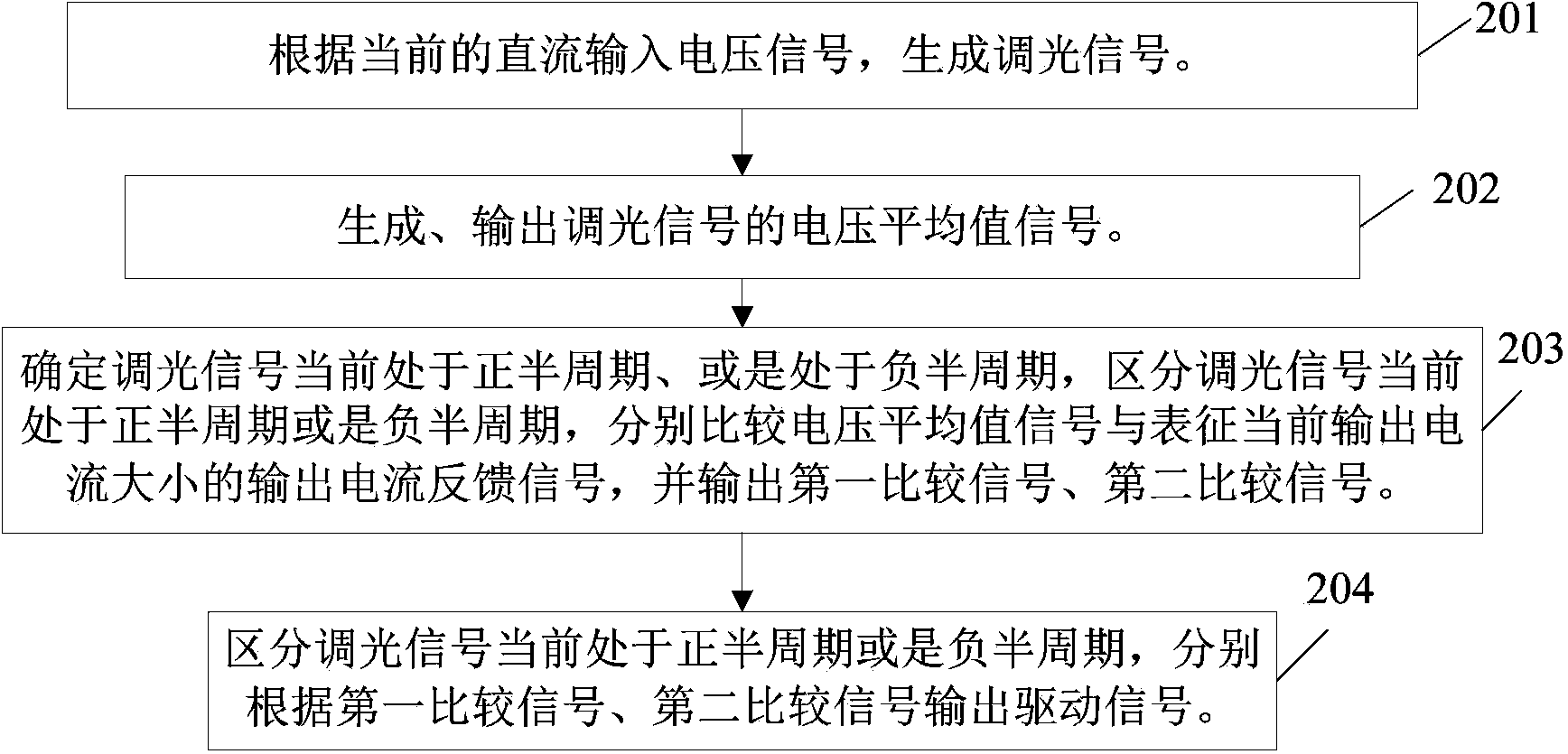
[0051] see figure 2 As shown, a dimming method applicable to thyristor dimming provided in this embodiment mainly includes the following steps:
[0052] Step 201: Generate a dimming signal according to the current DC input voltage signal.
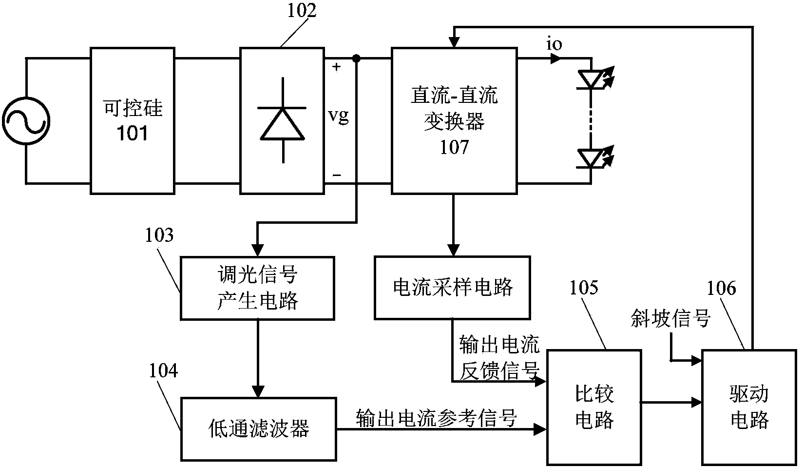
[0053] In actual circuit application, after the external AC input voltage signal is sent to the thyristor, the thyristor outputs an AC input voltage signal representing the current input value. After the signal is rectified, its corresponding DC input voltage signal is obtained, wherein the period and amplitude of the DC input voltage signal are the same as those of the AC input voltage signal.
[0054] In this step, after the DC input voltage signal is obtained, a dimming signal representing the current dimming angle is generated according to the current DC input voltage signal, and the dimming signal represents the dimming information desired by the current user.
[0055] Step 202: Generate and output an average voltage signal of the dimm
Embodiment 2
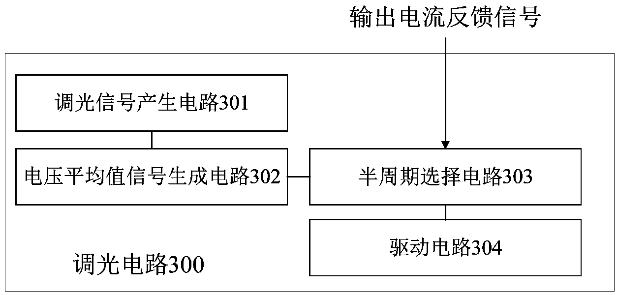
[0076] see image 3 As shown, a dimming circuit 300 provided in this embodiment mainly includes: a dimming signal generating circuit 301 , a voltage average signal generating circuit 302 , a half cycle selecting circuit 303 , and a driving circuit 304 . The connection relationship and working principle of each part are as follows:
[0077] The output end of the dimming signal generation circuit 301 is connected to the voltage average signal generation circuit 302, the half-cycle selection circuit 303 is connected to the output end of the voltage average signal generation circuit 302, and receives the output current feedback signal, and the driving circuit 304 is connected to the half-cycle The output terminal of the selection circuit 303 is connected.
[0078] Its working principle is: the input end of the dimming signal generation circuit 301 is connected to the DC input voltage signal rectified by the rectification circuit, and the dimming signal generation circuit 301 generat
Embodiment 3
[0091] This embodiment provides a schematic diagram of a specific circuit implementation structure of a dimming circuit and a specific implementation circuit of applying it to a thyristor dimming circuit.
[0092] see Figure 4 As shown, the difference between the dimming circuit 400 of this embodiment and Embodiment 2 mainly lies in:
[0093] As an illustration of this embodiment, the dimming signal generating circuit 301 of this embodiment mainly includes: a first comparator A1 and a voltage dividing circuit 401 .
[0094] Wherein the voltage divider circuit 401 is connected to the output terminal of the rectifier bridge 402, and is used to sample the current DC input voltage signal Vg obtained after rectification to obtain the input voltage sampling signal Vs. The second input terminal of the first comparator A1 (specifically The inverting input terminal "-") is connected to the output terminal of the voltage divider circuit 401 to receive the input voltage sampling signal Vs
PUM
 Abstract
Description
Claims
Application Information
 - R&D Engineer
- R&D Manager
- IP Professional
- Industry Leading Data Capabilities
- Powerful AI technology
- Patent DNA Extraction
Browse by: Latest US Patents, China's latest patents, Technical Efficacy Thesaurus, Application Domain, Technology Topic.
© 2024 PatSnap. All rights reserved.Legal|Privacy policy|Modern Slavery Act Transparency Statement|Sitemap