Plastic cement rough edge repairing machine

A repairing machine and burr technology, which is applied in the field of plastic product production, can solve problems such as excessive cutting, insufficient cutting, and high labor intensity, and achieve the effects of accurate repair, improved production efficiency, and high yield

Inactive Publication Date: 2014-02-19
陈德恩
View PDF5 Cites 2 Cited by
  • Summary
  • Abstract
  • Description
  • Claims
  • Application Information

AI Technical Summary

Problems solved by technology

However, there are many defects. It is difficult to grasp the accurate force due to manual cutting, either the c

Method used


Image

  • Plastic cement rough edge repairing machine
  • Plastic cement rough edge repairing machine
  • Plastic cement rough edge repairing machine

Examples


Embodiment Construction

[0015] The following embodiments will further illustrate the present invention in conjunction with the accompanying drawings.

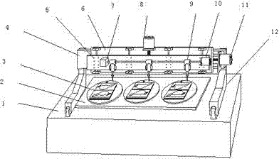
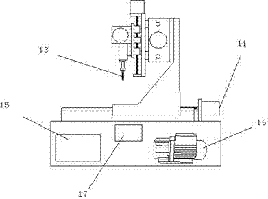
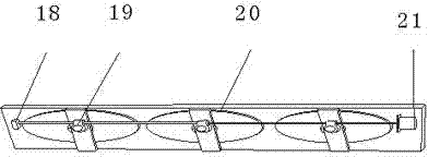
[0016] The plastic burr repairing machine uses the machine base (1) as the supporting body. The longitudinal sliding beam guide rail (12,) is installed on the machine base (1), and the horizontal sliding beam (6) is installed on the horizontal bracket (4) above the longitudinal sliding beam guide rail. The vertical sliding beam (5) is installed on the horizontal sliding beam, the blade (13) is locked on the tool rotation connector (9), the tool rotation angle detector (7) and the tool driving motor (10) and the tool rotation connector (9) ) installed on the vertical slide beam. The longitudinal sliding beam is driven by the motor (14) to reciprocate longitudinally; the horizontal sliding beam is driven to reciprocate horizontally by the motor (11); the vertical sliding beam is driven to reciprocate vertically by the motor (8). When the vertical sliding


PUM


Abstract

The invention discloses a plastic cement rough edge repairing machine, especially belongs to the field of rough edge repairing of plastic cement handicrafts. The plastic cement rough edge repairing machine comprises a lateral shifting shaft, a longitudinal shifting shaft, a vertical shifting shaft, a rotating work platform and a rotating cutting tool. According to the plastic cement rough edge repairing machine, driven by a control circuit, a stepping motor or a servo motor rotates based on a pre-set program, the rotating cutting tool is driven by the lateral shifting shaft, the longitudinal shifting shaft and the vertical shifting shaft to rotate along a pre-set path, so that rough edges at surface joints of plastic parts are cut by the blade of the rotating cutting tool. The rotating work platform reciprocates 180 DEG, so that the positions of two sucking moulds arranged on the work platform are exchanged by turns, one of the sucking moulds is used for cutting, and the other sucking mould is used for sucking a plastic part to be repaired. The plastic cement rough edge repairing machine can be used for repairing plastic pats instead of artificial operation, lack of cutting or over cutting is avoided, labor intensity is reduced, rate of finished products and working efficiency are increased.

Description


Claims


Application Information

Patent Timeline
Owner 陈德恩
Why Eureka
Try Eureka