Anti-corrosion sensor

A sensor and vibrator technology, applied in the field of sensors, can solve the problems of corrosion of internal components and poor sealing performance of anti-corrosion sensors, and achieve the effect of good sealing effect

Active Publication Date: 2016-08-24
CHONGQING CHUANYI AUTOMATION
View PDF9 Cites 0 Cited by
  • Summary
  • Abstract
  • Description
  • Claims
  • Application Information

AI Technical Summary

Benefits of technology

This patented technology improves on existing sensors by adding another layer called an anti-corrosion coating that helps protect it from corruption caused during use or other factors like temperature changes over time.

Problems solved by technology

This patented describes a method for improving the seal quality of a guide wavelength radio altimeter (GW) measurement system's inner component called the piston ring.

Method used


Image

  • Anti-corrosion sensor
  • Anti-corrosion sensor
  • Anti-corrosion sensor

Examples


Embodiment Construction

[0021] This specific embodiment provides an anti-corrosion sensor, which has better sealing effect.

[0022] The following will clearly and completely describe the technical solutions in the embodiments of the present invention with reference to the accompanying drawings in the embodiments of the present invention. Obviously, the described embodiments are only some, not all, embodiments of the present invention. Based on the embodiments of the present invention, all other embodiments obtained by persons of ordinary skill in the art without making creative efforts belong to the protection scope of the present invention.

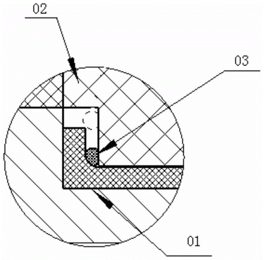
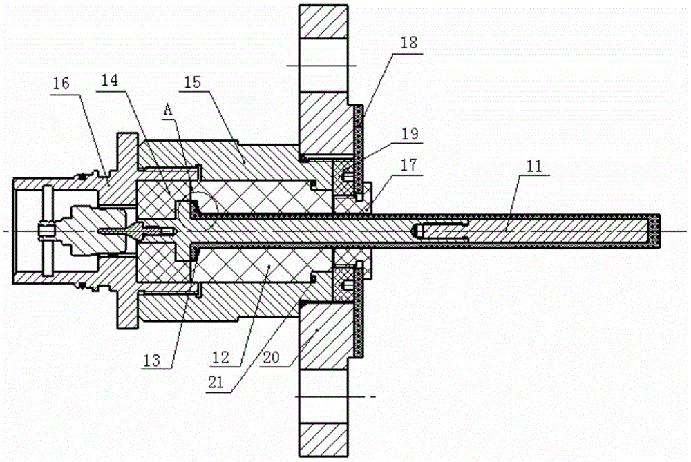
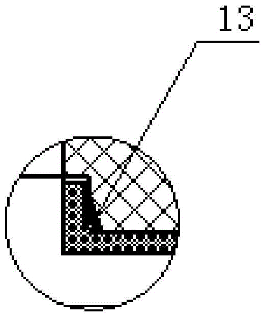
[0023] Please refer to figure 2 and image 3 , an anti-corrosion sensor provided in this specific embodiment, including a measuring assembly 11 with a shoulder structure, an anti-corrosion vibrator lower sleeve 12 sleeved under the shoulder structure of the measuring assembly 11, and a shaft sleeved on the measuring assembly 11 The upper anti-corrosion vibrato


PUM


Abstract

The invention discloses a corrosion-resisting sensor. The corrosion-resisting sensor comprises a measurement assembly with a shaft shoulder structure, a corrosion-resisting vibrator lower sleeve and a corrosion-resisting vibrator upper sleeve, wherein the corrosion-resisting vibrator lower sleeve is connected to the part below the shaft shoulder structure of the measurement assembly in a sleeved mode, the corrosion-resisting vibrator upper sleeve is connected to the part above the shaft shoulder structure of the measurement assembly in a sleeved mode, and the lower end face of the corrosion-resisting vibrator upper sleeve abuts against the upper end face of the corrosion-resisting vibrator lower sleeve. The corrosion-resisting sensor further comprises a lower connection sleeve and an upper connection sleeve, wherein the lower connection sleeve is connected to the corrosion-resisting vibrator upper sleeve and the corrosion-resisting vibrator lower sleeve in a sleeved mode, the head of the corrosion-resisting sensor is sleeved with the upper connection sleeve, a gap is arranged between the lower connection sleeve and the corrosion-resisting vibrator upper sleeve, and the upper connection sleeve can be embedded in the gap. Due to the arrangement, the corrosion-resisting sensor has a better sealing effect.

Description


Claims


Application Information

Patent Timeline
Owner CHONGQING CHUANYI AUTOMATION
Why Eureka
Try Eureka