Multifunction simulation power source used for distributed generation grid connection detection

A technology of distributed power supply and analog power supply, applied in electrical components, output power conversion devices, etc., can solve problems such as single AC or DC output characteristics, and achieve the effect of improving accuracy

Active Publication Date: 2014-04-23
STATE GRID CORP OF CHINA +2
View PDF4 Cites 7 Cited by
  • Summary
  • Abstract
  • Description
  • Claims
  • Application Information

AI Technical Summary

Problems solved by technology

Traditional simulation devices often can only simulate the output characteristics o

Method used


Image

  • Multifunction simulation power source used for distributed generation grid connection detection

Examples


Embodiment Construction

[0017] In order to make the technical means, creative features, goals and effects achieved by the present invention easy to understand, the present invention will be further described below in conjunction with specific embodiments.

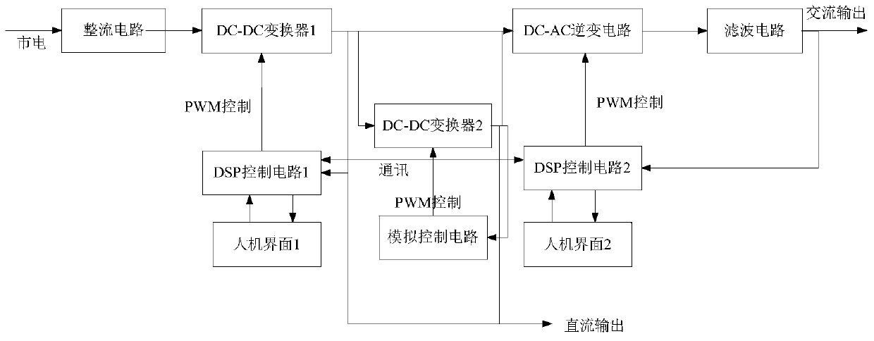
[0018] see figure 1 , the present invention can realize the simulation function including photovoltaic array power generation characteristics, wind turbine power generation characteristic simulation function, micro gas turbine power generation characteristic simulation function and the function of providing AC and DC equipment power for testing equipment and charging storage battery.

[0019] The mains power is used as the input of the first DC-DC converter after being rectified by the diode bridge, and the first DC-DC converter is PWM-controlled by the first DSP control circuit. The first DSP control circuit collects the output voltage and output current of the converter, and then controls the behavior of the converter according to the output charac


PUM


Abstract

The invention discloses a multifunction simulation power source used for distributed generation grid connection detection. The multifunction simulation power source is characterized by comprising a photovoltaic array electricity generation character analog module and a fan/micro-gas turbine electricity generation character analog module, wherein the photovoltaic array electricity generation character analog module comprises a rectifying circuit connected with a mains supply, a first DC (direct current)-DC converter connected with the output end of the rectifying circuit and used for providing power for direct current detection equipment, a first DSP (Digital Signal Processor) control circuit and a first human-computer interface connected with the first DSP control circuit; the fan/micro-gas turbine electricity generation character analog module comprises a DC-AC (alternating current) inverter circuit connected with the output end of the first DC-DC converter and used for providing power for alternating current detection equipment, a second DSP control circuit and a second human-computer interface connected with the second DSP control circuit. The simulation power source is capable of simulating the photovoltaic array electricity generation character, the fan electricity generation character and the micro-gas turbine electricity generation character and has the alternating current and direct current output characters.

Description


Claims


Application Information

Patent Timeline
Owner STATE GRID CORP OF CHINA
Why Eureka
Try Eureka